802 IB
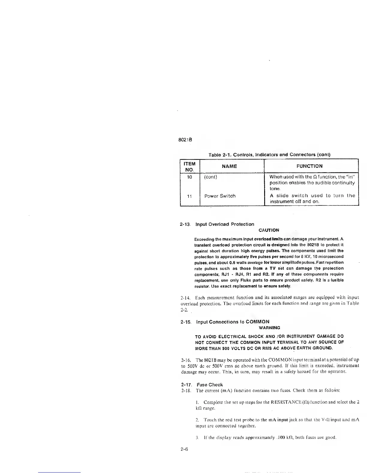
Table
2-1.
Controls,
Indicators and
Connectors (coot)
K59
NAME
FUNCTION
10
(cont) When used with the
ft
function,
the
“in”
position
enables
the audible continuity
tone.
Power Switch
A
slide switch used to- turn the
instrument off and on.
2-13. input Overload Protection
CAUTION
Exceeding the
maximum input
overload limits can damage your instrument. A
transient
overload
protection
circuit is
designed into the 8021 B to protect it
against
short duration
high energy puises. The
components used
limit the
protection
to
approximately five puises per second for 6 KV, 10
microsecond
pulses, and
about 0.8 watts average
for lower amplitude puises. Fast repetition
rate
puises such
as those from a TV set can
damage the protection
components; RJ1
-
RJ4, R1 and R2. If any of these components require
replacement,
use only Fluke parts
to ensure product safety. R2 is
a
fusible
resistor. Use
exact replacement to ensure safety.
2-14. Each
measurement
function and its
associated
ranges are equipped with input
overload
protection.
The overload limits for
each function and range are given in Table
2
-
2.
2-15. Input
Connections to COMMON
WARNING
TO AVOID
ELECTRICAL SHOCK AND /OR
INSTRUMENT DAMAGE DO
NOT
CONNECT THE
COMMON INPUT TERMINAL TO
ANY SOURCE OF
MORE THAN
500 VOLTS DC OR RMS
AC ABOVE EARTH GROUND.
2-
1 6. The
802 1 B may be
operated with the COM
MON input terminal at a
potential of up
to
500V dc or
500V
rms ac
above earth ground. If
this limit is exceeded,
instrument
damage may
occur. This, in turn, may
result in a safety hazard
for the operator.
2-17.
Fuse Check
2-18.
The current (mA) function contains
two fuses. Check them as
follows;
1. Complete
the
set up steps for
the RESISTANCE (fl) function and
select the
2
kil range.
2. Touch
the
red
test probe
to
the mA
input
jack so that the V-ft
input
and mA
input are connected together.
3. if the display
reads approximately
.100
kll, both fuses
are good.
2-6