8021
B
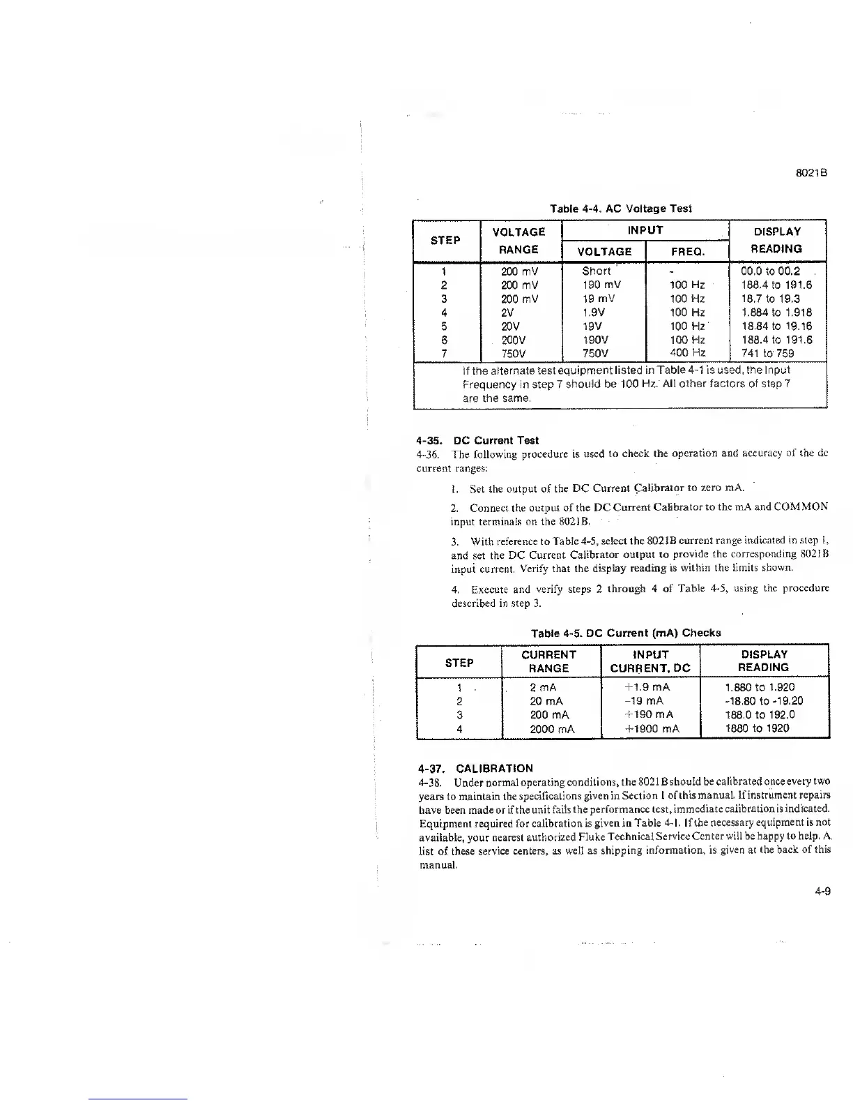
Table
4-4. AC Voltage Test
STEP
VOLTAGE
RANGE
INPUT
DISPLAY
READING
VOLTAGE
FREQ.
1 200
mV
Short
-
00.0 to 00.2
2 200 mV
190 mV 100 Hz 188.4 to 191.6
3
200
mV 19
mV
100 Hz
18.7
to 19.3
4 2V
1.9V 100 Hz
1.884
to 1.916
5 20V
19V 100 Hz 18.84 to 19.16
6
200V 190
V
100 Hz
188.4 to 191.6
7 750V
750V
400
Hz
741 to 759
if the
alternate test
equipment listed in Table
4-1
is used, the Input
Frequency in step 7
should be 100
Hz. All other factors of step
7
are
the same.
4-35.
DC
Current Test
4-36. The following
procedure is used to
check the
operation and accuracy of the
dc
current ranges:
1.
Set
the output of the DC
Current
Calibrator
to
zero mA.
2.
Connect the
output
of
the DC
Current Calibrator to
the
mA
and COM MON
input terminals on
the 802
IB.
3.
With reference to
Table 4-5, select
the 802 IB
current range
indicated in
step
1,
and set
the DC
Current Calibrator
output to
provide the corresponding 802 IB
input
current. Verify that
the display
reading is within the
limits shown.
4.
Execute and
verify steps 2 through
4 of Table
4-5, using the procedure
described in step
3.
Table
4-5.
DC
Current (mA)
Checks
STEP
CURRENT
RANGE
INPUT
CURRENT, DC
DISPLAY
READING
1 2
mA +1.9
mA
1.880 to
1.920
2
20 mA
-19
mA -18.80
to
-19.20
3 200 mA
+190 mA
188.0 to
192.0
4 2000 mA
+1900 mA
1880
to 1920
4-37. CALIBRATION
4-38.
Under
normal operating
conditions, the 8021
Bshould be calibrated once
every two
years to maintain
the specifications
given in Section 1 of
this manual. If instrument
repairs
have been made or if the
unit fails the
performance test,
immediate calibration is indicated.
Equipment required for
calibration is given in
Table
4-1
. If the
necessary equipment is not
available,
your
nearest
authorized Fluke Technical
Service Center
will be
happy
to help. A
list of these
service centers, as well
as shipping
information, is
given
at
the back of this
manual.
4-9