-BLACK
TEST LEAD
(-)
/
—RED TEST
/
LEAD
(+)
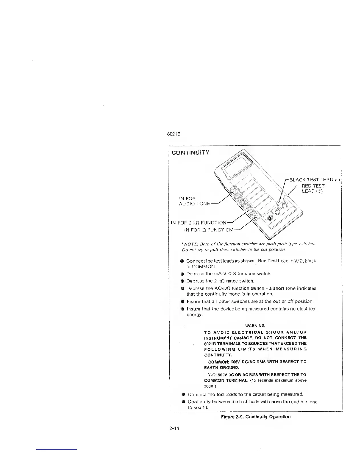
!N FOR
AUDIO TONE
'
60
,
•>
IN
FOR 2 l<Q
FUNCTION
—
'
IN FOR
Q
FUNCTION
#
NOTE:
Both
of
the function
switches are
push-push type switches.
Do not
try to
pull these switches to
the out position.
#
Connect the
test
leads as
shown
-
Red Test Lead
in
V/Q,
black
in
COMMON.
#
Depress the
mA-V-Q-S function switch.
#
Depress
the 2 kfi range switch.
® Depress the
AC/DC function
switch
-
a short tone indicates
that the continuity mode
is in operation.
%
Insure that all other switches
are
at
the out or off position.
9
Insure that the device being
measured contains
no
electrical
energy.
TO AVOID
ELECTRICAL SHOCK
AND/OR
INSTRUMENT
DAMAGE. DO NOT CONNECT THE
8021 B
TERMINALS TO SOURCES
THAT EXCEED THE
FOLLOWING
LIMITS WHEN
MEASURING
CONTINUITY.
COMMON:
500V DC/AC RMS
WITH RESPECT TO
EARTH GROUND.
V-Q: 500V DC OR
AC RMS WITH RESPECT THE TO
COMMON
TERMINAL.
(15
seconds maximum above
300V.)
Connect the test leads to
the circuit being measured.
Continuity between the test leads will cause the audible tone
to
sound.
Figure
2-9. Continuity Operation
2-14