APPENDIX 1
Checking the Sensitivity of
Counters
Introduction
The sensitivity of a counter is normally specified as the
minimum signal voltage on which the input of the
counter will trigger correctly.
When you use a signal-source with an output-imped-
ance of 50Ω, constant-output-amplitude, and the
counter has a 50Ω input-impedance, the input signal of
the counter is in theory independent of the cable length.
However, if the input impedance deviates from 50Ω
there will be standing wave reflections which will cause
changes in the amplitude of the signal between the sig-
nal-source and the counter input.
Two factors determine the magnitude of the changes,
i.e. frequency and capacitive load.
EXAMPLE:For a 1 M
Ω
//35 pF input, the 35 pF parallel
capacitance is approximately equal to a 50
Ω
capacitive load at 100 MHz.
Consequently, it is of the utmost importance to know
how sensitivity is measured.
Recommended Instruments
– Signal-source with a 50Ω output impedance.
– >350 MHz oscilloscope with a 50Ω input impedance.
– BNC T-piece.
– Two BNC-cables, one short and one long.
High-Impedance Inputs (1 MΩ)
Preparations
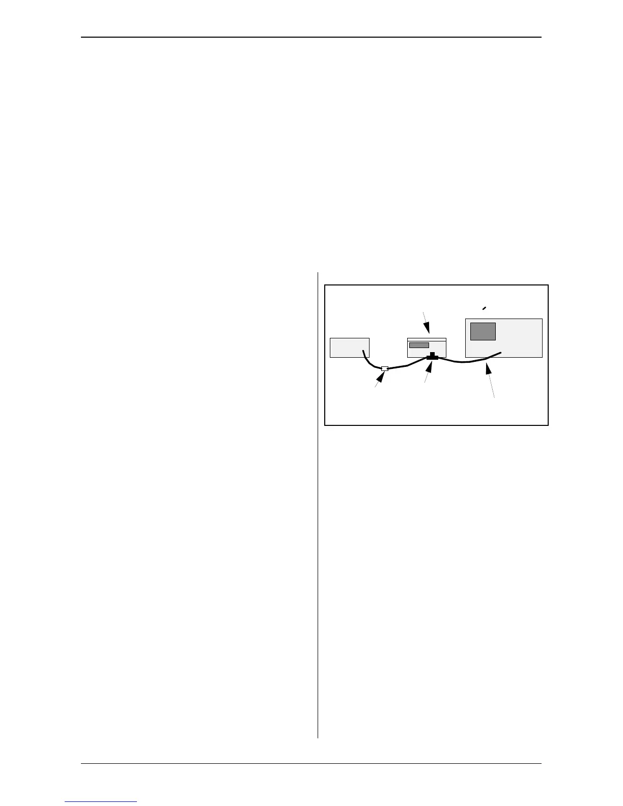
Connect the instruments as illustrated in the figure
above. Set the counter to maximum sensitivity.
Method 1
– Adjust the amplitude of the signal-source to the mini-
mum level accepted by the counter.
– Read the amplitude on the oscilloscope.
– Check that the reading is the same as, or less than,
the sensitivity level in the counter specifications.
Method 2
– Adjust the amplitude of the signal-source until the oscil-
loscope indicates the sensitivity limit in the counter
specifications.
– Check that the counter is operating correctly.
Low-Impedance Inputs (50Ω)
If you have a calibrated signal-source
– Adjust the signal-source to the sensitivity limit of the
counter.
Signal source
Counter
under test
Oscilloscope
350 MHz
T-piece
Attenuator
(if required)
Shortest cable
possible
directly
on counter
50 ohm
>
50 ohm
APPENDIX 1 Page: 41
PM 6669 - OPERATORS MANUAL