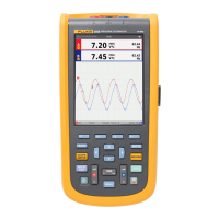
Do you have a question about the Fluke ScopeMeter 215C and is the answer not in the manual?
Bandwidth | 200 MHz |
---|---|
Sample Rate | 2.5 GS/s |
Input Channels | 2 |
Display | Color LCD |
Vertical Resolution | 8 bits |
Timebase Range | 5 ns/div to 100 s/div |
Input Coupling | AC, DC, GND |
Vertical Sensitivity | 2 mV/div to 100 V/div |
Battery Life | 4 hours |
Input Impedance | 1 MΩ |
Safety Rating | CAT IV 600 V |
Max Input Voltage | 1000 V (DC + peak AC) |
Operating Temperature | 0 °C to +50 °C |
General overview of safety information and precautions in the manual.
Details on safety procedures, cautions, and warning statements.
Explanation of symbols used for safety on the test tool and in documentation.
Procedures for handling impaired safety conditions.
General safety guidelines for operating and servicing the test tool.
Overview of the illustrated list of replaceable parts by assembly and item number.
Instructions on how to locate and order spare parts from a service center.
Detailed list of parts for the final assembly of the test tool.
Components list for the main Printed Circuit Assembly (PCA) unit.
Lists standard and optional accessories for the ScopeMeter test tool.
Overview of performance tests to ensure proper operation and calibration.
List of essential instruments and cables for performing verification tests.
Guidelines for powering, warming up, and conducting tests.
Procedures for resetting the tool, navigating menus, and creating test setups.
Steps to check the functionality and brightness of the display and backlight.
Detailed procedures for verifying accuracy of Scope Inputs A and B.
Procedure to verify the external trigger level function.
Procedures for verifying the accuracy of the multimeter functions.
Test to verify the internal probe calibration square wave generator.
Overview of calibration process, requirements, and cycle.
Outline of the steps required for complete and partial calibration.
Steps to enter calibration mode and adjust the test tool date.
Procedure to adjust display darkness, default contrast, and brightness.
Steps for the essential warming-up and pre-calibration phase.
Procedures for performing the final calibration adjustments.
Steps to calibrate the Low/High Frequency Gain for Input A.
Steps to calibrate the Low/High Frequency Gain for Input B.
Steps to calibrate the Low/High Frequency Gain for both Inputs A&B.
Procedure for calibrating the position of Inputs A&B.
Steps to calibrate the Voltage Gain for Inputs A&B.
Procedure to calibrate the Voltage Gain for the Digital Multimeter.
Steps for calibrating the zero point for Inputs A&B and DMM.
Procedure to calibrate the Ohm Gain for the Digital Multimeter.
Steps to calculate gain and save calibration data, then exit.
Adjusting voltage probes for optimal response.
Overview of disassembly procedures and safety precautions.
Comprehensive guide for taking apart and putting back together the test tool.
Lists the necessary tools for accessing and removing components.
Procedure to detach the tilt stand and hang strap from the unit.
Instructions for replacing or repositioning the side-strap.
Steps to open the casing and remove the battery pack.
Procedure to remove the main circuit board and cooling fan.
Steps to detach the display unit from the test tool.
Procedure for replacing the LCD window or decal.
Steps to remove the keypad and its foil.
Detailed steps for disassembling the main PCA unit.
Precautions and steps for reassembling the main PCA unit.
Overall procedure for reassembling the test tool after disassembly.