Performance Verification
4.8 Meter (DMM) Tests
4
al55ex4w.bmp
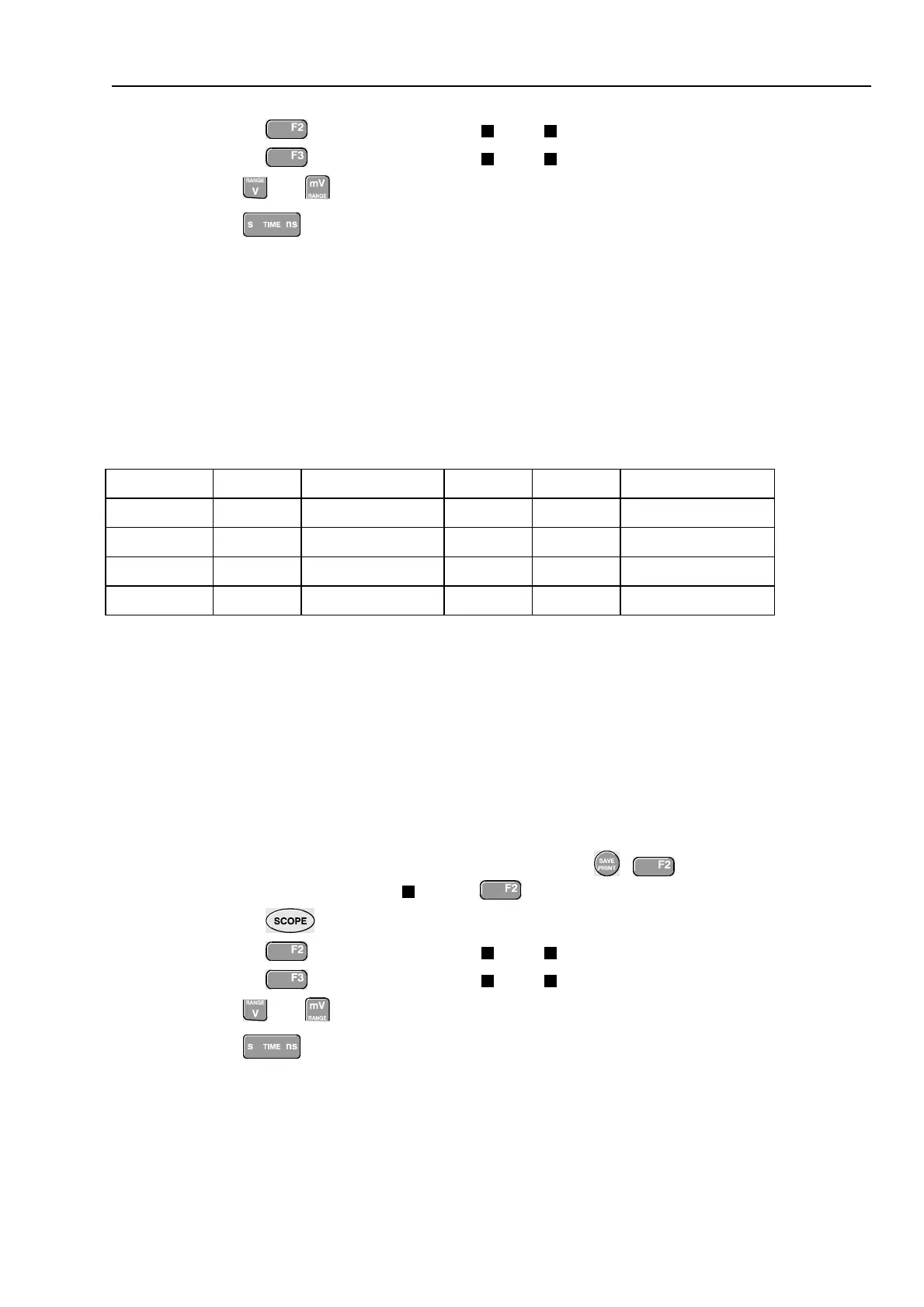
Figure 4-19. Test Meter Tool Input to 5500A Normal Output 4-Wire
2.
Select the following test tool setup:
•
Press
•
Press
to open the Measurement menu, and select
Ohms
•
Press
to select AUTO ranging.
3.
Set the 5500A to source the appropriate resistance value for the first test point in
Table 4-14.
Use the 5500A “COMP 2 wire” mode for the verifications up to and including
50 kΩ. For the higher values, the 5500A will turn off the “COMP 2 wire” mode.
4.
Observe the reading and check to see if it is within the range shown under the
appropriate column.
5.
Continue through the test points.
6.
When you are finished, set the 5500A to Standby.
Table 4-14. Resistance Measurement Verification Points
5500A output Meter Reading
0Ω 0.0 to 0.5
400Ω 397.1 to 402.9
4 kΩ 3.971 to 4.029
40 kΩ 39.71 to 40.29
400 kΩ 397.1 to 402.9
4 MΩ 3.971 to 4.029
30 MΩ 29.77 to 30.23
To verify the internal probe calibration square wave generator, you can do a Probe
Calibration as described in section 5.8. If no square wave appears on the screen, either
• the probe is defective: try another probe, check the probe with an external voltage in a
scope application,
or
• the internal square wave generator is defective.
4.9 Probe Calibration Generator Test