Calibration Adjustment
5.1 General
5
5.1 General
5.1.1 Introduction
The following information, provides the complete Calibration Adjustment procedure for
the ScopeMeter test tool (referred to as test tool). The test tool allows closed-case
calibration using known reference sources. It measures the reference signals, calculates
the correction factors, and stores the correction factors in RAM. After completing the
calibration, the correction factors can be stored in FlashROM.
The test tool should be calibrated after repair, or if it fails the performance test. The test
tool has a normal calibration cycle of one year.
5.1.2 Calibration number and date
When storing valid calibration data in FlashROM after performing the calibration
adjustment procedure, the calibration date is set to the actual test tool date, and
calibration number is raised by one. To display the calibration date and - number:
1. Press , then press to see the Version & Calibration data (see Figure 5.1).
2. Press
to return to exit the Version & Calibration screen.
wm-verscal.bmp
Figure 5-1. Version & Calibration Data
Note:
The calibration date and calibration number will not be changed if only the
Contrast Calibration Adjustment and /or the Probe Calibration is done
5.1.3 General Instructions
Follow these general instructions for all calibration steps:
• Allow the 5500A to satisfy its specified warm-up period. For each calibration point ,
wait for the 5500A to settle.
• The required warm up period for the test tool is included in the WarmingUp &
PreCal calibration step.
• Ensure that the test tool battery is charged sufficiently.
• Power the test tool via the BC190 Battery Charger/Power Adapter
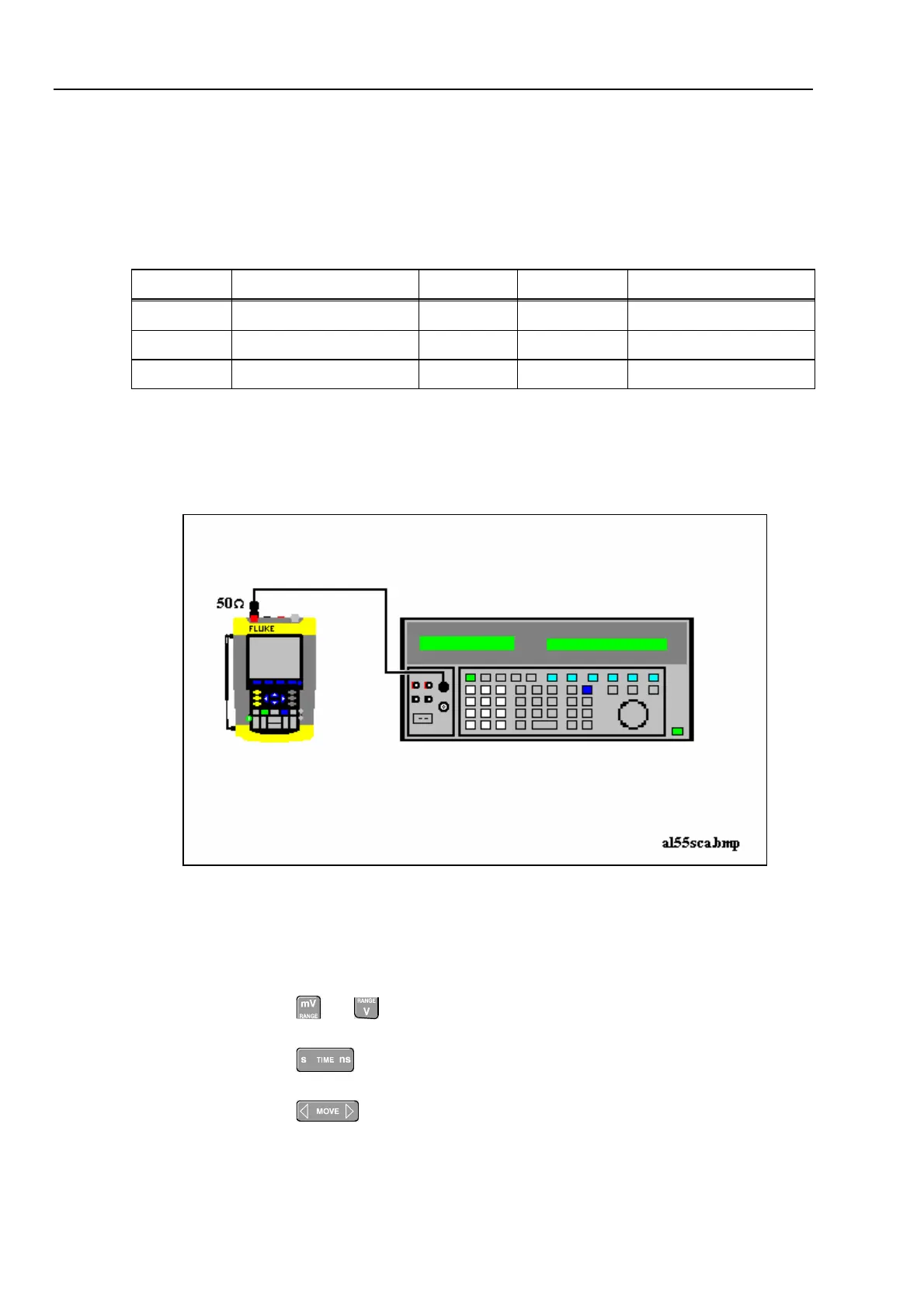
5.1.4 Equipment Required For Calibration
The primary source instrument used in the calibration procedures is the Fluke 5500A. If
a 5500A is not available, you can substitute another calibrator as long as it meets the
minimum test requirements.