28
Bit 3: Reserved.
Bit 2: Cash Drawer “DOUT bit0” pin output control.
= 1: Opening the Cash Drawer
= 0: Allow closing the Cash Drawer
Bit 1: Cash Drawer “DOUT bit1” pin output control.
= 1: Opening the Cash Drawer
= 0: Allow closing the Cash Drawer
Bit 0: Reserved
Note: Please follow the Cash Drawer control signal design to control the Cash
Drawer.
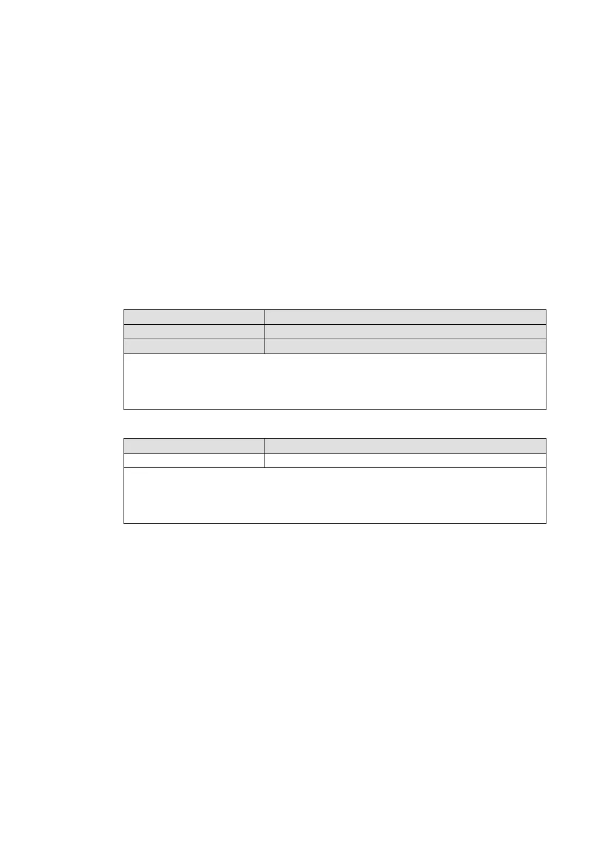
4-6-3 Cash Drawer Control Command Example
Use Debug.EXE program under DOS or Windows98
Command Cash Drawer
O 4B8 04 Opening
O 4B8 00 Allow to closing
¾ Set the I/O address 4B8h bit2 =1 for opening the Cash Drawer by
“DOUT bit0” pin control.
¾ Set the I/O address 4B8h bit2 = 0 to allow closing Cash Drawer.
Command Cash Drawer
I 4B8 Check status
¾ The I/O address 4B8h bit4 =1 means the Cash Drawer is closed or no
Cash Drawer.
¾ The I/O address 4B8h bit4 =0 means the Cash Drawer is open.