OPERATING TTHE FFIRE
Turn on the power supply and momentarily press the ON switch on the
control box located to the right of the control knob. The fan should oper-
ate with the warning light illuminated. Almost immediately the fan will
slow down to operating speed and a click may be heard as the safety sole-
noid opens allowing gas to the burner unit. The warning light on the con-
trol box should extinguish.
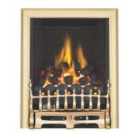
The pilot is visible through the left hand side of the front coal strip. Push
in and turn the control knob to the SPARK position, and hold there for a
few seconds.
Continue turning anti-clockwise through the spark click to the PILOT light position, ensuring the pilot has lit. If
not, return the knob clockwise, and repeat.
When the pilot lights after the spark, keep the knob depressed for approximately ten seconds. Now release the
knob and the pilot should stay alight. If not, retry ignition. If the pilot is extinguished during use of the fire, wait
three minutes before repeating the ignition procedure.
To achieve the HIGH setting, push the control knob in slightly and continue turning anti-clockwise to the high
position. The main burner should light after a few seconds. To decrease the setting to LOW, turn the control knob
clockwise to the low setting. To turn to the PILOT position from the HIGH or LOW positions, press the control
knob in, and return to the pilot position and release. To turn the fire OFF, keep the knob pressed in, return to the
off position and release. Press the OFF button on the control box to switch off the fan.
SPARK FAILURE
The gap between the spark electrode and the pilot should be 3.5 - 4.5mm to produce a good spark. There should
be no need to adjust this. If under any circumstances the electric spark fails, the pilot may be lit manually by pro-
ceeding with the ignition sequence as previously described, and after turning the control knob through the spark
position, the knob should be held in and the pilot lit with a taper.
SETTING PRESSURE
Remove the screw from the pressure test point, situated on the main injector pipe by the pilot, and attach a U
gauge. Light the fire on the HIGH setting. The setting pressure should be in accordance with the figures stated
on page 2 of these instructions. The fire is factory set to achieve these pressures, and any significant variation
could indicate a supply problem. If the pressure is too high, the gas supply meter may be set incorrectly. This
should be checked with the fire running and if necessary reset by the gas supplier.
If the pressure is too low, then check the meter governor pressure with the appliance running. If this is incorrect
it will need to be reset by the gas supplier. If the setting pressure is too low, but the meter pressure is acceptable,
then a problem in the supply pipework is to be suspected. This will be dirt and debris, kinked or inadequate size
pipes, restriction in a fitting or solder flashing across a joint.
Note: yyou wwill nnot gget aan aaccccurate rreadingg oof tthe iinlet ppressssure wwith aa ppressssure ggaugge oon tthe eend oof tthe ssupply
pipe - tthiss iiss tthe sstaticc ppressssure iin tthe ssysstem. YYou mmusst uusse aa TT ppiecce aand mmeassure tthe ssupply ppressssure wwith tthe
fire oon HHiggh - tthe ddynamicc ppressssure.
SPILLAGE MONITORING SYSTEM
This fire is fitted with a flue spillage safety device (ODS). If the fire shuts down during use for no apparent reason
then several things may be suspected. If a door or window has been opened creating a draught, then pilot
disturbance is the problem, and removal of the draught should resolve this. If a grommet seal has been left out
of the firebox then this also will also cause intermittent shutdown (recall your installer to fit). The gas pressure
reaching the fire must also be checked (again, recall your installer to check and rectify any problem). The
thermocouple connection into the back of the gas control valve may also have worked loose during installation,
simply get the installer to tighten.
177
11.1
11.2
11.3
11.4