DISMANTLING TTHE BBURNER TTRAY - ccontinued
The filter element should also be blown clean. This component should not require replacement, however if signs
of deterioration are evident then a genuine spare must be used. If a large amount of debris is present in the filter
then the pipework and control should be thoroughly cleaned before re-assembly.
CHECKING THE FAN ASSEMBLY
Disconnect the electrical supply, and remove the fan terminal cover. Check all components for signs of deterio-
ration paying attention to the wiring, and ensuring all electrical connections are good.
Remove the terminal from the wall and check the flue tube is in the correct position. Check the flue is free
from obstruction along its entire length. Clean outlet and airflow sensors with a suitable brush. Clean fan vanes
and remove any debris. Ensure sealing rings are in position. Refit the terminal to the wall. Ensure that no plants
etc. obscure the exhaust outlet.
Reconnect the electrical supply and check the operation of the fan. Press the ON switch, the fan should build
up speed with the warning light illuminated and then rest at normal operating speed. The light on the control
box should extinguish. The safety solenoid on the burner tray should now open. Establish a pilot flame but DO
NOT light the main burner. Block the fan outlet with a piece of card. The fan should build up speed in an effort
to clear the ‘obstruction’, when this fails the pilot will be extinguished and the fan cut out. When you are sure
the operation is correct, refit the terminal cover and wire cage.
CONTROL BOX RREMOVAL
Disconnect the electrical supply and isolate the gas supply. Remove the burner tray as previously described in
the relevant section. Remove the two securing screws and lift away the control box heatshield. Slide the control
box to the left off its mounting bracket, and remove the multiway connector from the rear.
Replacement is reverse of removal, taking care to ensure the box is mounted securely and each individual con-
nector pin makes good contact with the control box pin.
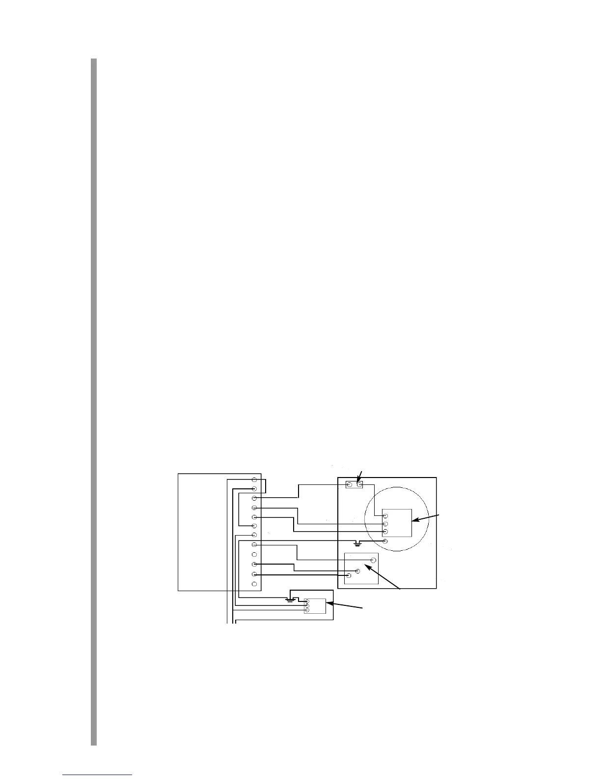
SScchheemmaattiicc ooff aapppplliiaannccee wwiirriinngg
20
13.2
13.3
13.4
Control Box
Thermal Switch
Fan
Pressure switch
Safety solenoid
Mains supply