PREPARING FOR INSTALLATION ((continued)
Apply the self adhesive sealing strip to the rear perimeter of the firebox frame so as not to be visible. This will
eventually seal the firebox to the fireplace back panel. Place the fire to one side whilst the site is prepared for flue
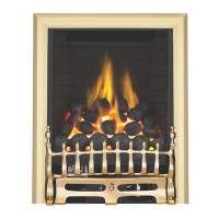
installation. Mark the vertical centreline of the desired
location of the appliance after first checking for clearances
to pipes and cables in the wall, and also the terminal posi-
tion outside.
Note: TThe vverticcal ccentreline oof tthe ppilot hhole wwill bbe
500mm ffrom tthe ffloor PPLUS the tthiccknessss oof tthe hhearth
you aare uussingg. TThiss ddimenssion iiss oobvioussly FFROM the
hearth ttop ssurfacce iif iit iiss aalready ffitted
Mark the position of the 30mm cable hole in relation to
the flue centreline. Using a suitably long masonry bit, drill
through both leaves of the cavity wall. Check outside that
the clearances from the hole are adequate for installation
to proceed. Check all dimensions with the diagram in the
relevant section. Now drill the 30mm cable hole in the
wall.
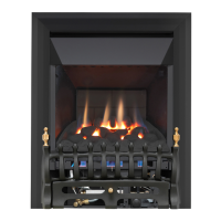
OUTER WALL APERTURE
From the outside of the property, open up the pilot hole in the
external leaf of the cavity to the required size.
If the fan terminal is to mounted directly onto the outside wall,
the hole should be opened up to a 125mm diameter aperture
centred around the pilot hole.
If the fan terminal is to be recessed into the outer leaf, the hole
should be opened up to the dimensions given in the diagram.
Clear all the brick rubble and debris that may have fallen into the
cavity. If the cavity wall insulation is obstructing your view of the
inner leaf then clear this back.
GAS SUPPLY ROUTES
The gas supply may enter the appliance across the hearth or through the ‘knock outs’ provided in the rear of the
firebox. Gas pipes should not be buried or routed through walls without being protected by conduit or sleeving.
An isolation tap must be included in the gas connection pipe to facilitate servicing.
Note: AAny ffittinggss uussed uunderneath tthe aappliancce
musst bbe rrated tto 880
o
C aand mmusst nnot ccome iinto ccon-
tacct wwith tthe uundersside oof tthe bburner uunit
For INSTALLATION METHOD 1, the gas supply can
be run in the conventional manner taking due
account of rules and regulations.
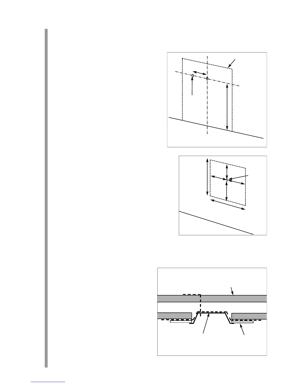
For INSTALLATION METHOD 2, use only factory
sleeved pipe in a continuous unjoined length in the
cavity of the wall and area which communicate with
the cavity. Ensure a good seal where the pipe enters
through the appliance grommet. This is a permitted
gas supply routing.
6
8.1
8.0
Proposed location of appliance
120mm
500mm
plus
thickness of
hearth
Centreline of flue
Cable routing hole
257-267mm
297-
307mm
118mm
105mm
Pilot hole
139mm
192mm
Cavity
Outer leaf
Fireplace panel
Firebox
8.2