SERVICING ((continued)
15. Turn on the gas supply, and leak test.
16. Re fit the front panel of the fire, and the control knob.
17. Check any purpose provided ventilation is un-obstructed.
18. Light the fire and test for spillage.
19. Check setting pressure and safe operation of the appliance.
For specific servicing instructions, see the relevant sections.
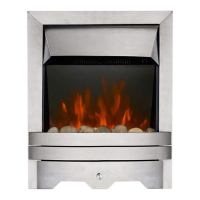
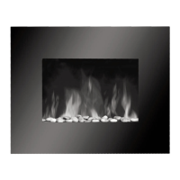
CLEANING TTHE CCERAMICS ((Glass/pebble mmodels)
WARNING: The glass crystals remain hot for a considerable time after the appliance has been turned off. It is rec-
ommended that the appliance be left to cool for at least two hours before any part of the fuel bed is removed for
cleaning.
Wear pprotective ggloves wwhen hhandling tthe gglass ccrystals.
Remove the ceramic components. Gently clean in the open air. Be careful not to create dust from the pebbles.
Where necessary replace damaged components with genuine spares. Seal scrap components in plastic bags and
dispose of at proper refuse sites as directed.
Re-fit the pebbles carefully by referring to the relevant section of these instructions.
If necessary, the glass crystals may be removed from the firebowl and cleaned in lukewarm mild soapy water.
Rinse thoroughly in clean water and ensure the glass in completely dry before refilling.
CLEANING TTHE CCERAMAT
Any debris or dust that has accumulated on the mat may be carefully removed with a vacuum cleaner. DO NOT
use sharp objects or tools to clean the mat as this may damage the mat.
CLEANING TTHE FFIREBOX
Stainless steel parts of the fire may be cleaned using a soft damp cloth or stainless steel cleaner.
IMPORTANT: Always clean in the direction of the grain, and never across it as this will scratch the surface. It is
recommended that a small area is attempted before cleaning the entire stainless steel area - to ensure the clean-
ing material is suitable.
DISMANTLING TTHE BBURNER UUNIT
Remove the burner unit as previously described. The pilot unit can be removed by undoing the tubing nut, the
thermocouple nut on the rear of the valve, lint arrestor, two securing screws, and lifting away. Remove the tubing
nut from the valve end of the pilot pipe, and blow through to dislodge any debris that may be present. Clean the
exterior of the pilot assembly with a soft brush and blow through the flame ports on the pilot head. Check the
aeration holes are free from lint or dirt. The pilot assembly is a non-serviceable item, and should not be taken
apart. The aeration hole must be absolutely clear internally for proper operation. A thoroughly cleaned (inside
and out) oxypilot will cure a wide range of ignition faults. The injector pipe can now be checked for debris.
Remove the two tubing nuts on the ends of the gas pipe to the injector elbow. The injector pipe can now be
checked for debris. Remove the air shutter from the injector bracket by removing two screws. Remove the nut
retaining the injector elbow. Blow through the elbow to remove any debris.
The valve is not field serviceable, apart from the pilot filter. Remove the largest of the three screws on the face
of the valve. Slide the filter out and clean away any debris that may have accumulated. The filter element should
also be blown clean. This component should not require replacement, however if signs of deterioration are evi-
dent then a genuine spare must be used. If a large amount of debris is present in the filter then the pipework and
control should be thoroughly cleaned before re-assembly.
10
15.1
15.0
15.2
15.3
15.4