GAS SSUPPLY RROUTING
Following preparation for the fixing method, the concealed gas
supply, where required, can now be put into place.
IMPORTANT - Wherever a concealed connection is made a
rubber grommet must be used to seal the firebox.
The gas pipe must be suitably protected where it passes
through fireplace openings. Any sleeving should be sealed to
the pipe at its ends. This appliance is fitted with an inlet restic-
tor elbow. The elbow is located to the right of the gas valve.
The open end of the 8mm supply pipe should be sealed tem-
porarily during the installation of the firebox to prevent the
ingress of dirt and dust during fixing.
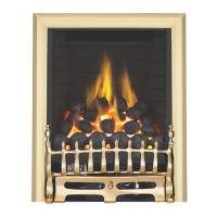
FITTING THE FIREBOX
The firebox may be fitted to the opening by using screw fixing or by the cable kit as described in the relevant sec-
tion. Leave the polythene coating in place unitl fitting procedures are complete to eliminate any risk of scratch-
ing the decorative finish. Fit the firebox, ensuring the fire sits fully back in the opening.
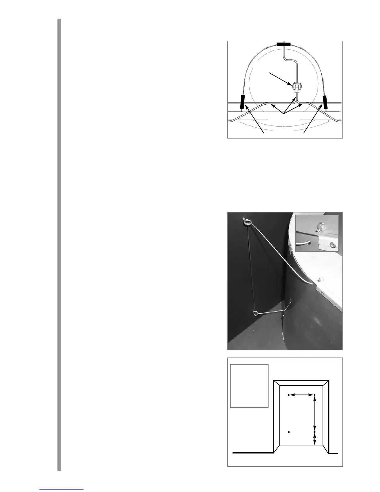
CABLE FIXING
Drill four holes as shown in the diagram and fit the fibre rawl plugs. If the fireplace does not allow for the exact
layout shown, the eyebolts should be fixed to give a similar configuration as possible.
Thread both tensioning cables through the holes at the top of
the firebox (inset), both eyelets, and back through the lower
holes in the firebox as shown.
Before finally fitting the firebox, ensure the self-adhesive seal-
ing strips are in position around the rear of the firebox frame.
Push the appliance back into the fireplace, centralise and pull
the loose cables through the holes into the firebox. Thread the
cable tensioners onto the cables as shown, with the nuts
screwed down close to the tensioner head.
Slide the screwed nipple onto the cable, pull cable taut and
tighten nipple. Adjust tensioner using a suitable spanner to
pull the appliance back into position, to allow an even seal
around the fireplace opening. Visually inspect the seal and
reseat if necessary.
Surplus tension cable MUST NOT be cut off as this will pre-
vent proper installation after servicing. Coil up the surplus
cable and store in the rear of the firebox.
GAS CONNECTION
Refit the burner unit into the firebox, fit the four screws through
the locating holes in the rim of the burner, and tighten. Purge
the gas supply thoroughly to remove air and dirt/debris
BEFORE
connection. Now disconnect the inlet restrictor elbow
from the inlet pipe.
Connect the previously installed gas supply to inlet restrictor
elbow, and re-fit the restrictor elbow to the inlet pipe of the
appliance.
If using an across hearth connection, ensure the decorative fire-
frame and front panel will clear the supply route.
6
10.0
Inlet
Restrictor
Elbow
Supply Routes
Rubber Grommet
11.0
11.2
11.1
A
B
C
A. 325 mm
B. 420 mm
C. 100 mm
Dimension ‘A’
can be +/-
10mm