PREPARING TTHE AAPPLIANCE
Note: EEnssure tthat tthe ggass ssupply iiss iissolated bbefore ccom-
menccingg iinsstallation oof tthe aappliancce.
The fireplace opening and environment must be in com-
pliance with the specifications laid down in the appropri-
ate sections of these instructions.
Remove the appliance from it’s carton as described previ-
ously and stand upon a dust sheet or similar. Place the
decorative frame, ceramics (if applicable) and fixings safe-
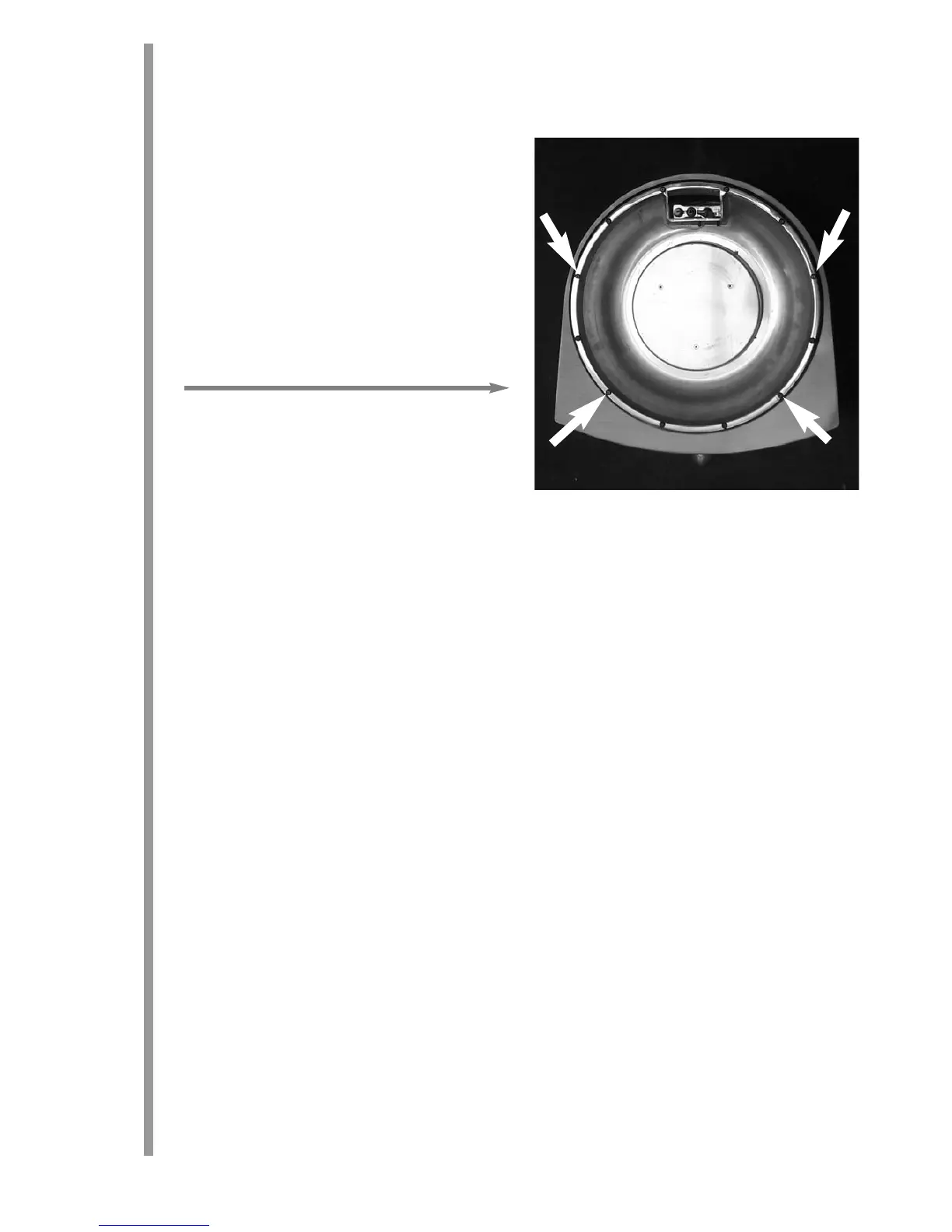
ly to one side. The burner unit may be removed from the
stainless steel firebowl by removing the four screws
shown. An allen key is provided for this purpose.
It is also necessary to remove the control knob. This is
achieved by removing the grub screw at the rear of the
knob. With the knob removed, the front panel of the
appliance may be lifted off to allow access to the gas
valve, pressure test nipple and appliance inlet.
Knockout holes are provided in the sides and rear of the firebox for use where concealed pipework is required.
Where necessary, knock out the appropriate hole with a sharp tap from a hammer, and fit the rubber grommet
supplied. A small incision can how be made in the rubber to slip snugly around the outside of the pipe and sleev-
ing.
Do nnot iinsstall oor uusse tthe aappliancce wwithout tthe ssealss iin pplacce
.
If a hole is inadvertently opened, reseal with an
intact grommet. Failure to fit the seal correctly will cause flue suction to act upon the area under the burner, result-
ing in poor performance and possible intermittent cutting out of the burner.
PREPARING TTHE OOPENING
Before installing the fire, check the flue using a smoke pellet. All of the smoke should travel up the flue and exit
correctly from the terminal. If problems are found, DO NOT fit the fire until corrective action is completed.
Protect the hearth surface whilst pushing the firebox in and out of the opening. Part of the packaging makes an
ideal hearth saver pad. Before running the gas supply into the opening, offer up the firebox to the fireplace to
check the fit is good. Ensure that it slides in correctly, the sealing face sits flat and square to the wall or infill panel,
and that the base is firm on the floor of the opening as no leaks are permissible here. At this stage it is essential
to ensure that the spigot outlet of the fire is not restricted in any way. Remove the firebox and take any necessary
measurements before making good and preparing for final installation. Apply the self adhesive sealing strips
around the edge of the rear of the firebox frame, approximately 5mm in from the edge.
CABLE FIXING. For fixing of the fire by the cable method, see the relevant section. The cable fixing locations
should be marked on the back of the opening and the holes drilled. Fit the fibre rawlplugs and eyebolts to these
holes.
Note: PPlassticc rrawlpluggss aare NNOT ssuitable ffor tthiss aappliccation.
SCREW FIXING. For fixing by screw, mark and drill the fireframe or base, and the relevant points in the opening
or on the wall. Rawlplugs will again be required. Pre-punched holes are not provided for this purpose to allow
you to choose the optimum positions.
5
8.0
9.0