7
Hardware Features
Front Panel
4
5
4
5
8 9
13
1414
11
1
2
67 10 123
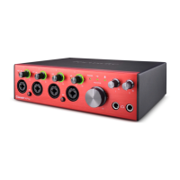
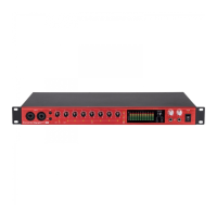
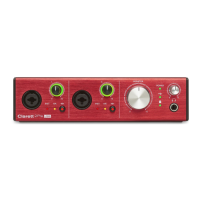
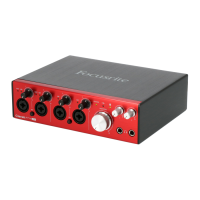
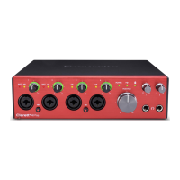
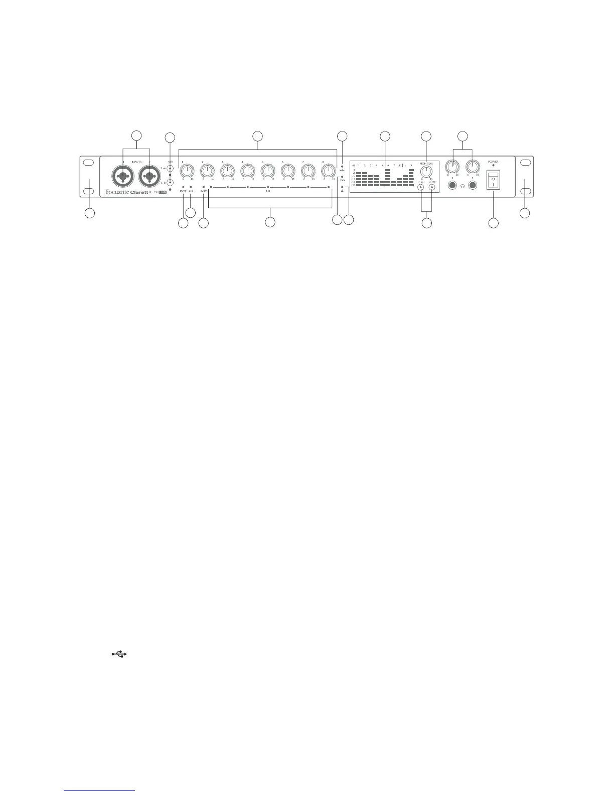
The front panel includes all the input gain and monitoring controls as well as two of the input
connectors for Mic, Line and Instrument signals.
1. INPUTS 1 & 2 – Combo XLR input sockets - connect microphones, instruments (e.g., guitar), or
line level signals via XLR or ¼” jacks as appropriate. Either TRS (balanced) or TS (unbalanced)
jack plugs can be used for instruments or line level signals.
2. 48V – two switches enabling 48 V phantom power at the XLR contacts of the Combo connectors
for mic inputs 1-4 and 5-8 respectively. (Note that inputs 3 to 8 are on the rear panel.) Each
switch has an associated red LED indicating that phantom power is selected. Note that
phantom power is
only
required by condenser and active ribbon mics; do
not
select phantom
power when using dynamic mics.
3. Gain 1 to 8 – eight rotary controls: adjust the input gain for the signals at Inputs 1 to 8
respectively.
4. INST – two red LEDs which illuminate when INST mode is selected for the jack contacts of
Inputs 1 or 2 from Focusrite Control software. When INST is selected, the gain range and input
impedance are altered (relative to LINE), and the input is made unbalanced. This optimises
it for the direct connection of instruments via a 2-pole (TS) jack plug. When INST is off, the
inputs are suitable for the connection of line level signals. Line level signals may be connected
either in balanced form via a 3-pole (TRS) jack or unbalanced, via a 2-pole (TS) jack.
5. AIR – eight yellow LEDs – one per input – which illuminate when the AIR function is selected
for the input from Focusrite Control. AIR modifies the frequency response of the input stage
to model the classic, transformer-based Focusrite ISA mic preamps.
6. Meters – ten 6-segment LED bargraph meters indicating a) the signal levels of the eight
analogue input signals (meters 1 to 8), and b) the signal levels at the MONITOR 1 and 2
outputs (meters L and R). The input meters show signal level after the input gain stage, and
thus their indication is affected by the gain controls. The output meters show signal level
before the monitor level control [10], which therefore does not affect their indication. The
LEDs illuminate at -42 (green, “signal present”), -18 and -12 dBFS (green), -6 and -3 dBFS
(yellow) and 0 dBFS (red). A level of 0 dBFS implies digital clipping, and should always be
avoided.
7. (USB active) – a green LED which illuminates when the unit has established communication
with the computer to which it is connected.
8. MIDI – a green LED which illuminates when MIDI data is being received at the rear panel
MIDI IN port.