6
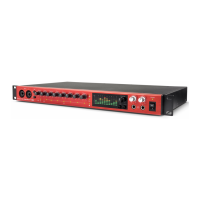
Hardware Features
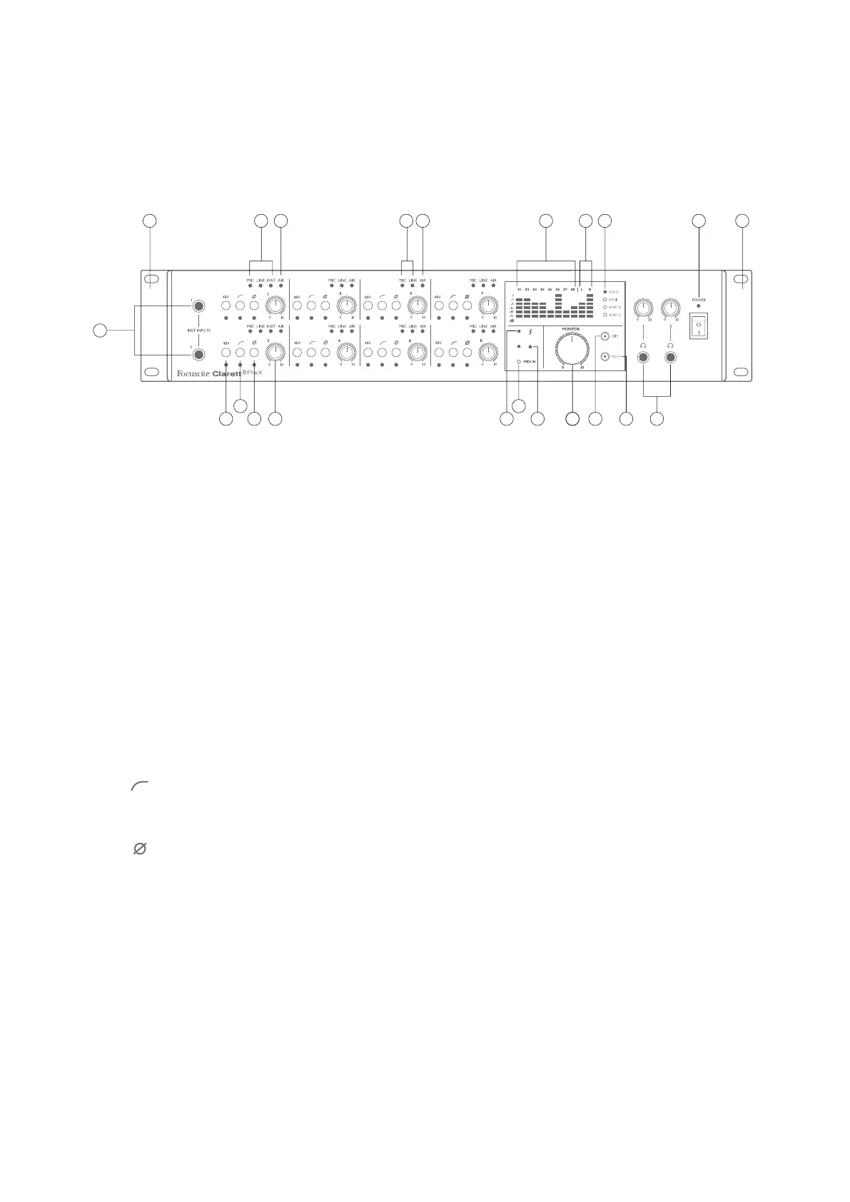
Front Panel
5 4
6
7
13
151512 1614 16 17
1
2 819 198 11 183 109
Repeated for each channel
Repeated for channel 2 Repeated for channels 3 to 8
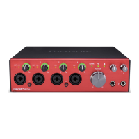
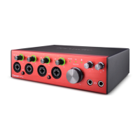
The front panel includes all the input gain controls and monitoring controls as well as two input
sockets for instrument jacks and two headphones sockets.
1. INST INPUTS – 2 x high impedance inputs on ¼” TS jack sockets for Channels 1 and 2: connect
a musical instrument (e.g., guitar) here.
2. MIC, LINE & INST – two sets of three red LEDs indicating the input currently selected for
Channels 1 and 2. Mic/Line/Inst selection is made from Focusrite Control.
3. MIC & LINE – six pairs of red LEDs indicating the input currently selected for Channels 3 to 8.
Mic/Line selection is made from Focusrite Control.
4. Input gain controls 1 to 8 – eight rotary controls: adjust the input gain for the signals in
Channels 1 to 8 respectively.
5. 48V – one switch per channel: enables 48 V phantom power at the corresponding rear panel
XLR mic input. Each switch has an associated red LED indicating that phantom power is
selected.
6. Hi-pass filters – one switch per channel: use to remove unwanted low-frequencies.
Filter is -3 dB at 80 Hz with a slope of 12 dB/octave. Each switch has an associated red LED
indicating that the filter is active.
7. Phase reverse – one switch per channel. Each switch has an associated red LED indicating
that the phase is reversed.
8. AIR – eight yellow LEDs – one per channel; illuminate when the AIR function is selected
from Focusrite Control. AIR modifies the frequency response of the input stage to model the
classic, transformer-based Focusrite ISA mic preamps.
9. Input signal level meters: eight LED bargraphs, one per channel. Segments indicate -42, -18
& -12 dBFS (green), -6 & -3 dBFS (yellow) and 0 dBFS (red). Input signals are metered post
the input gain controls, so you can see the levels being sent to the DAW.
10. Output signal level meters: two LED bargraphs indicating the signal level at Outputs 1 and 2.
Indications as input meters. Output signals are metered pre the monitor level control, so the
volume you have set is independent of the meter indications.