6
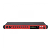
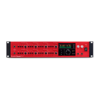
Rear Panel
17
15
18
19
16
1620222223
21
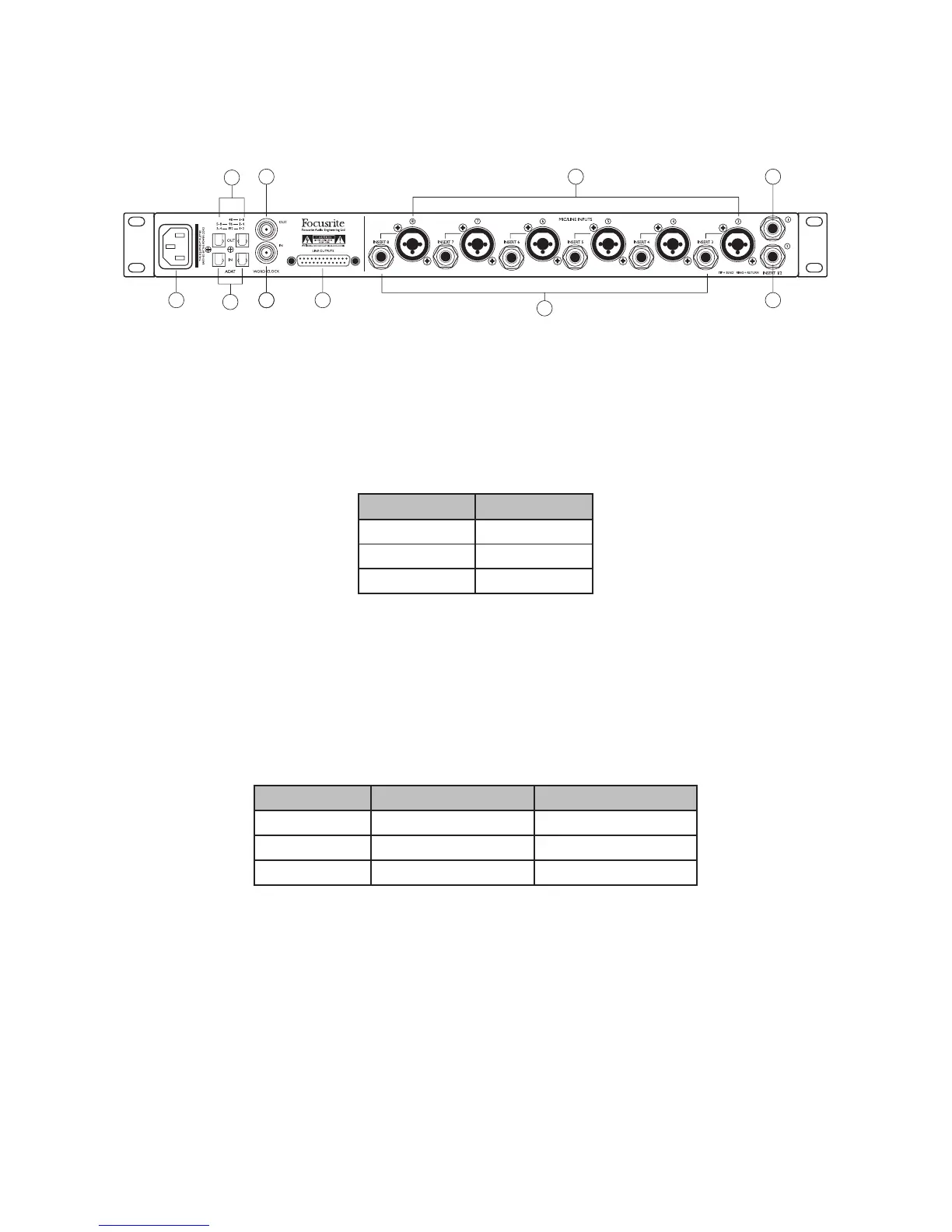
The remainder of the Clarett OctoPre’s inputs and outputs are on the rear panel.
15. INPUTS 3 to 8 – 6 x “Combo XLR” connectors; note that the inputs for Channels 3 to 8 do not
have INST mode, but are otherwise identical to those for Channels 1 and 2.
16. INSERTS 1 & 2 – two ¼” TRS jack sockets, providing an access point for connecting external
processing equipment into Channels 1 and 2. The inserts are enabled by the front panel
INSERT/AIR switches [6] and [8], and are unbalanced. The sockets are wired as follows:
Jack contacts Function
Tip Return (input)
Ring Send (output)
Sleeve Ground
Note that the front panel O/L LED [5] monitors signal level pre the insert send so that excessive
signal level is not sent to external equipment.
17. INSERTS 3 to 8 – 6 x ¼” TRS jack sockets providing the insert points for Channels 3 to 8; these
are electrically identical to [16].
18. OPTICAL OUT – two TOSLINK connectors providing the digital outputs of the unit. Utilisation
of the two connectors is sample rate-dependent, as follows:
Sample Rate OUTPUT 1 (RH port) OUTPUT 2 (LH port)
44.1/48 kHz Channels 1 to 8 Channels 1 to 8
88.2/96 kHz Channels 1 to 4 Channels 5 to 8
176.4/192 kHz Channels 1 & 2 Channels 3 & 4
19. OPTICAL IN – two TOSLINK connectors providing the digital inputs to the unit when used
in the ADAT > LINE mode. Note that these are NOT “digital” inputs to Channels 1 to 8, and
signals applied at these ports do not pass through the AIR circuitry, nor are available at the
inserts. Utilisation of the two connectors is sample rate dependent, as [18].
 Loading...