4
HARDWARE FEATURES
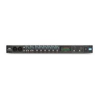
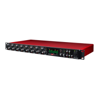
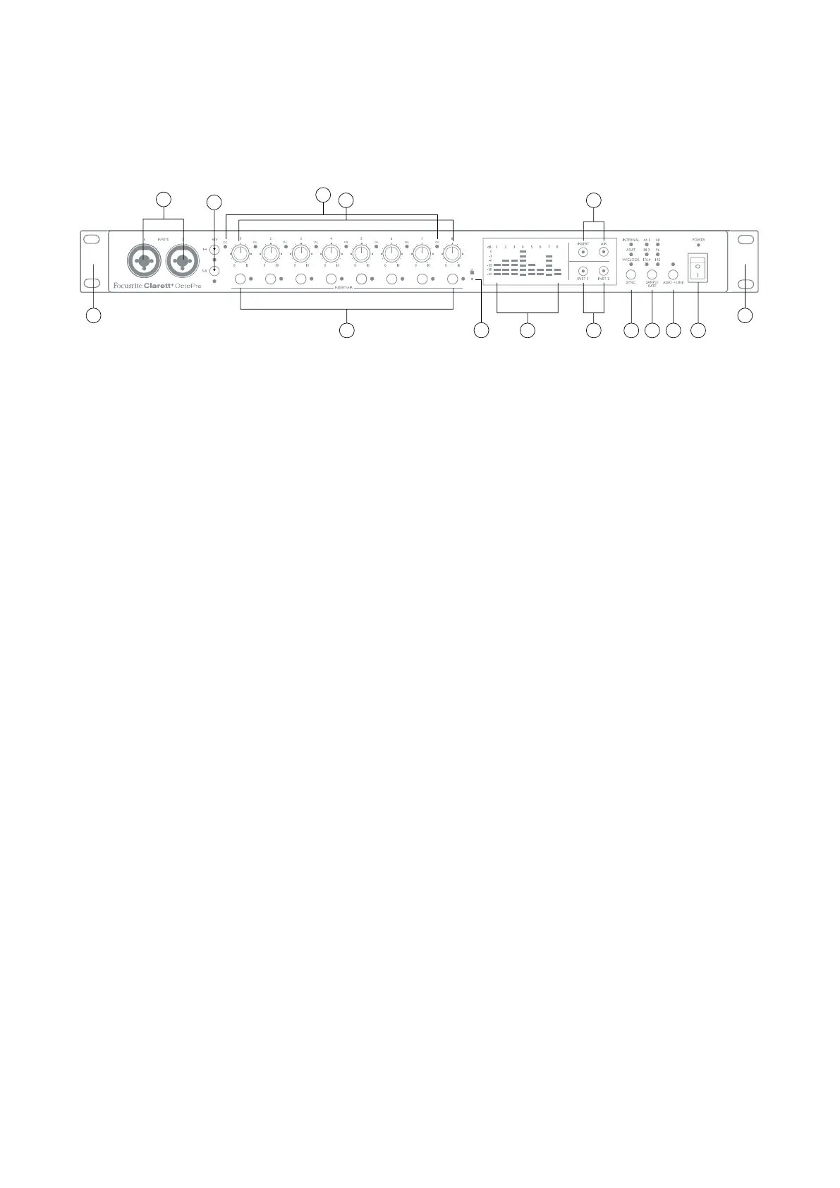
FRONT PANEL
11
139 1210
1414
1
3
4
5
6
2
8
7
1. INPUTS 1 & 2 – Combo XLR input sockets - connect microphones, instruments (e.g., guitar), or
line level signals via XLR or ¼” jacks as appropriate. Either TRS (balanced) or TS (unbalanced)
jack plugs can be used for instruments or line level signals.
2. INST 1 & INST 2 – two switches to set Inputs 1 and 2 to “Instrument” mode. When INST is
selected, the gain range and input impedance are altered (relative to LINE), and the input is
made unbalanced. This optimises it for the direct connection of instruments via a 2-pole (TS)
jack plug. When INST is off, the inputs are suitable for the connection of line level signals. Line
level signals may be connected either in balanced form via a 3-pole (TRS) jack or unbalanced,
via a 2-pole (TS) jack. Each switch has a red LED to confirm choice.
3. 48V – two switches enabling 48 V phantom power at the Combo connectors’ XLR contacts
for mic inputs 1-4 and 5-8 respectively. (Note that inputs 3 to 8 are on the rear panel.) Each
switch has a red LED to show when phantom power is enabled. Note that not all microphones
require phantom power. If you are unsure whether your microphone needs it to work, please
read the microphone documentation.
4. Gain 1 to 8 – eight rotary controls: adjust input gain for signals at Inputs 1 to 8 respectively.
5. O/L – each input channel has a red “overload” LED; this illuminates when the signal level
reaches +19.5 dBu. Always adjust the level so the LED does not illuminate: to avoid clipping.
6. INSERT/AIR – one switch per channel, which enables either the rear panel insert point for
the channel, or the channel’s AIR function, depending on the setting of the INSERT and AIR
main switches [8]. Each switch has an associated LED, which illuminates green when INSERT
is selected or yellow when AIR is selected.
7. Meters – ten 6-segment LED meters indicating a) the signal levels of the eight analogue
input signals (meters 1 to 8), and b) the signal levels at the MONITOR 1 and 2 outputs (meters
L and R). The input meters show signal level after the input gain stage. The output meters
show signal level before the monitor level control [10], which therefore does not affect their
indication. The LEDs illuminate at -42 (green, “signal present”), -18 and -12 dBFS (green), -6
and -3 dBFS (yellow) and 0 dBFS (red). 0 dBFS implies digital clipping, and should always be
avoided.
8. INSERT and AIR function main switches: two switches with internal LEDs
(INSERT = green, AIR = yellow) which determine the function of the per-channel INSERT/AIR
switches [6].
9. SAMPLE RATE – a switch which steps through the six sample rate settings. The current rate
is shown by a green LED. The OctoPre stores the sample rate in use so it is retained through
power cycles.