8
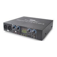
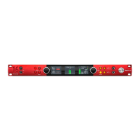
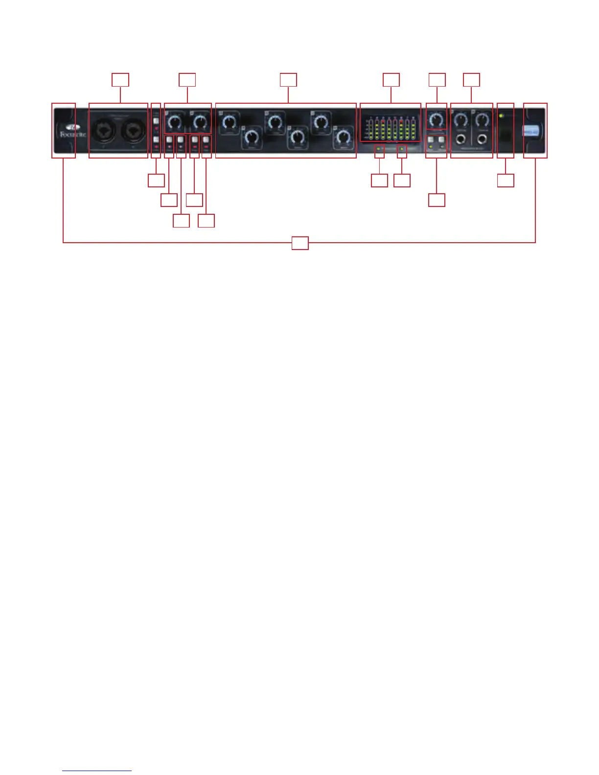
Front Panel
The Front Panel includes the input connectors for Channels 1 and 2, as well as all the input gain controls and monitoring controls.
1. Channel 1 and 2 Combo XLR input sockets. Each socket will accept an XLR, or 1/4 inch TRS (balanced) or TS (unbalanced)
Jack connector
2. Two Phantom power switches with LED’s for Mic inputs 1-4 and 5-8
3. Channel 1 and 2 Gain control knobs – use these to set the level of your input signal
4. Instrument switch with LED
5. Pad switch with LED. Maximum Signal input level without pads is +7dBu, with pads is +16dBu
6. Channels 3 to 8 Preamp Gain control knobs. – use these to set the level of your input signal
7. Signal level meters for analogue inputs 1-8: -42, -18, -6, -3, 0dBFS LEDs
8. Firewire active LED - Lit when the Saffire PRO 40 is successfully connected to the computer
9. Synchronisation Lock LED – Lit when Saffire PRO 40 is either syncronised to its internal clock, or to an external digital input
10. Monitor Level control pot. – Can be configured to control any number of the analogue outputs
11. Monitor Dim and Mute switches with associated LEDs
12. Headphones 1 & 2 level control and output 1/4 inch jacks
13. Power switch and LED indicator. Lit when the unit is receiving power and is turned on
14. Removable rack ear covers – remove when fitting to a 19 inch rack
1 127 106
14
3
2 138 9
4 11
5 5
4