10
DISPENSER
Left junction box
GND
GRN
B
W
Right junction box
BL
Y
RD
W
B
Lower junction box
(24V bin signal)
Ice machine #2
(optional)
W
B
X
GND
GRN
B
W
Lower junction box
(24V bin signal)
Ice machine #1
(optional)
Upper junction box
(power)
X
GND
GRN
B
W
Upper junction box
(power)
LEGEND
X
EQUIPMENT
GROUND
WIRENUT FIELD
CONNECTIONS
B BLACK
W
WHITE
GRN
GREEN
BL BLUE
Y
YELLOW
RD
RED
X
GND GRN
W
B
W
R
Lower ice machine
junction box
(bin signal)
B
Dispenser
junction box
X
W
GND GRN
Upper ice machine
junction box
(power)
B
Electric
power
source
Electric
power
source
Electric
power
source
Electric
power
source
Electric
power
source
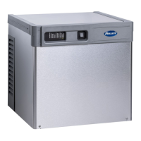
Recommended junction box preparation of
hard-wired RIDE model ice machines.
1. Cut plugs from supplied power cords.
2. Replace upper (power) strain relief with
a cord connector.
3. Mount two 2" x 4" junction boxes using
supplied holes in ice machine face.
4. Make power and bin signal connections.
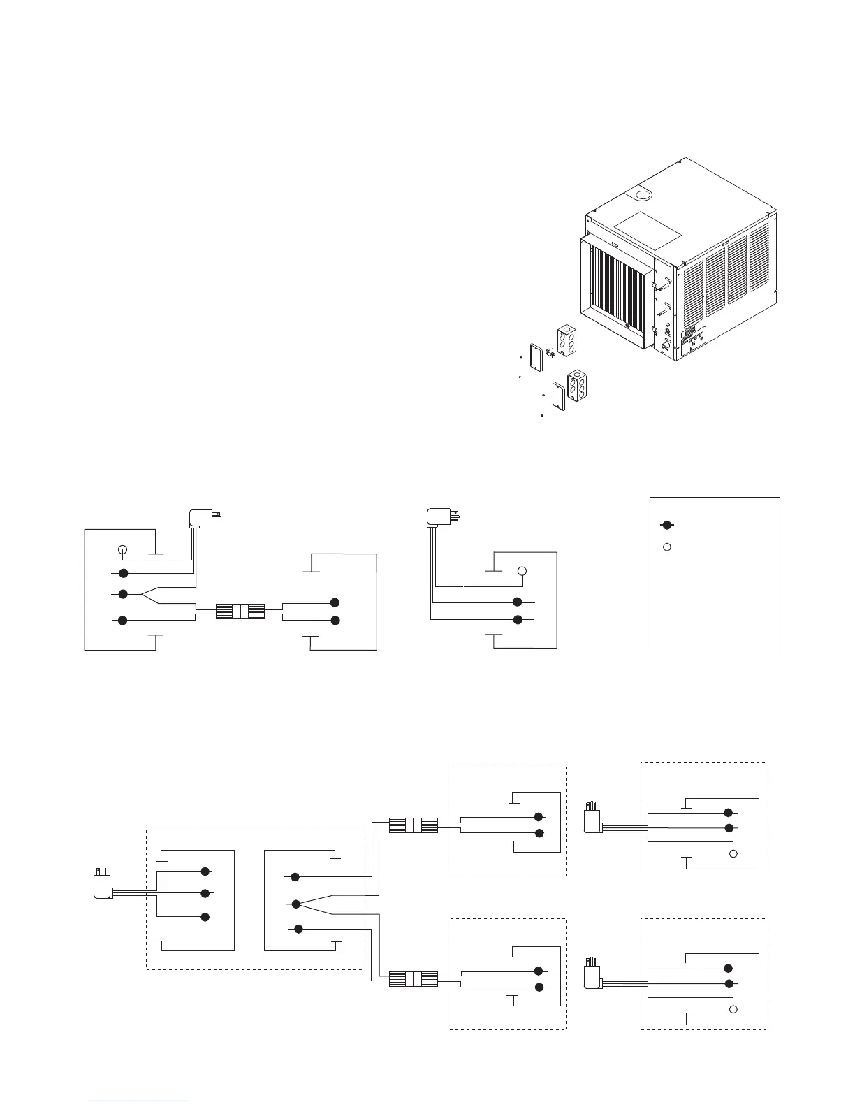
Field wiring diagrams for RIDE model ice machine installations
All eld wiring must be installed in accordance with NEC and local electrical codes.
Field wiring diagram is intended only to aid electrician or technician in understanding how equipment works.
Should local codes require a hard-wired connection and/or shielded wiring, eliminate the cord and plug(s) and
follow the appropriate eld wiring diagram.
MCD400A/W and R400A/W ice machines have separate power supply from dispenser.
Electric disconnects required within 10 ft (3m) for all hard-wired connections.
25, 50 or 110 ice and water dispenser with ONE RIDE model ice machine
(dispenser models 25CR400A/W, 25HR400A/W, 50CR400A/W, 50HR400A/W, 110CR400A/W)
VU155/VU300 ice and beverage dispenser with ONE or TWO RIDE model ice machines
Note: 24V bin signal; Verify black bin signal wire is on the 24V terminal