7
20.75" (527mm)
22.75" (578mm)
13.00"
(331mm)
4.875"
(124mm)
2.375"
(61mm)
1.875" (48mm)
7.00" (178mm)
A
A
B
B
F
F
D
E
C
A
B
C
C
17.00"
(432mm)
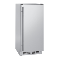
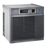
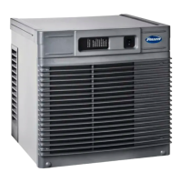
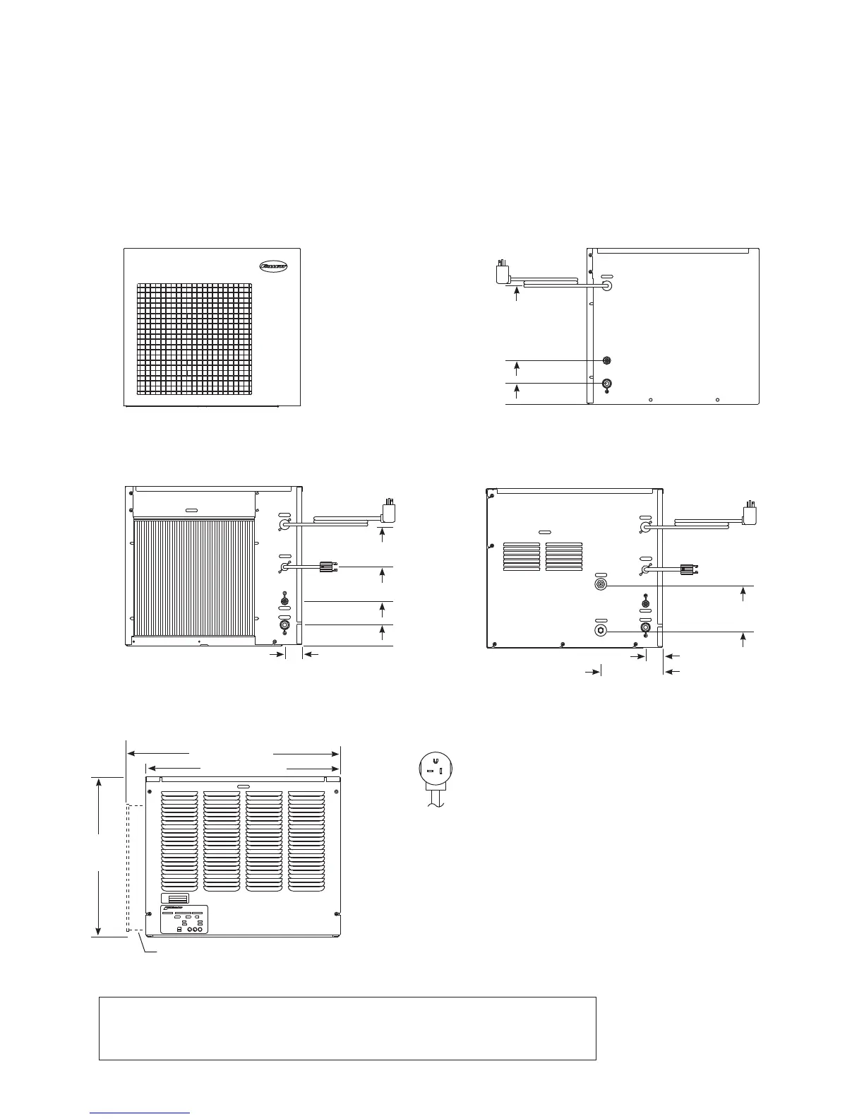
Front view — air-cooled
RIDE model
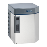
Side view — air-cooled and water-cooled
top mount and RIDE model
RIDE model air-cooled units only
Back view — air-cooled
top mount
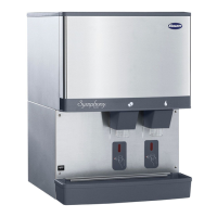
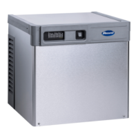
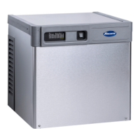
Front view — water-cooled
RIDE model
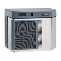
Back view — water-cooled
top mount
12.875"
(327mm)
4.75"
(121mm)
8.375"
(213mm)
2.25"
(57mm)
1.875" (48mm)
Front view — air-cooled
top mount
Ice machine plug
configuration
NEMA 5-20
6.875"
(175mm)
2"
(51mm)
Dimensions and clearances
Entire front of ice machine must be clear of obstructions/connections to allow removal.
12" (305mm) clearance above ice machine for service.
6" (153mm) minimum clearance between exhaust side of ice machine and any adjacent equipment.
MCD400A & R400A – 18" (457mm) minimum, 10 ft (3m) maximum clearance between discharge and air
intake grilles.
A – 3/4" MPT drain
B – 3/8" OD push-in water inlet
C – Electrical cord
D – 3/8" FPT condenser inlet
E – 3/8" FPT condenser drain
F – Bin signal cord