5.
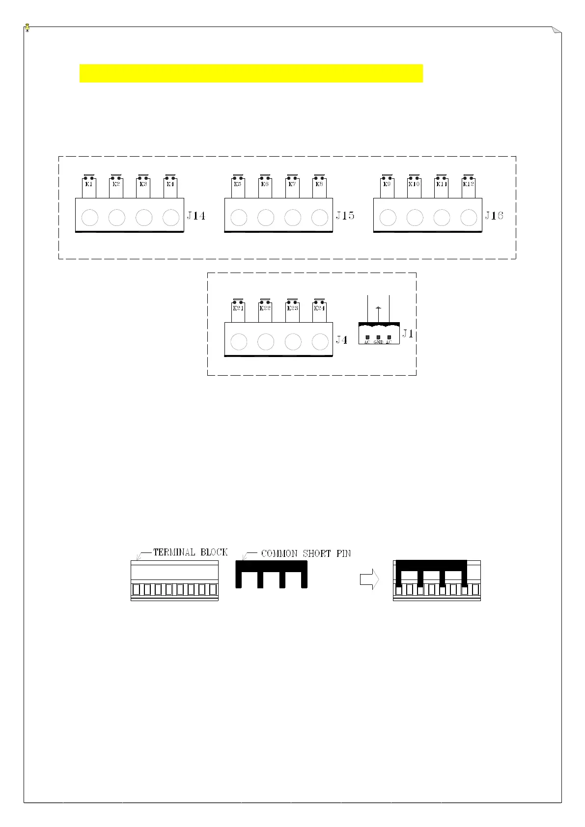
OUTPUT CONTACT DIAGRAM
5
5
.
.
1
1
A
A
l
l
p
p
h
h
a
a
3
3
0
0
0
0
0
0
F
F
2
2
O
O
u
u
t
t
p
p
u
u
t
t
C
C
o
o
n
n
t
t
a
a
c
c
t
t
UPPER RELAY BOARD
BOTTOM RELAY BOARD
U1
U2 E1
E2
N1
N2D2
D1
W1
W2
S1 S2
ID
MAIN
AUX
Note A: AUX output contact represents the 7
th
pushbutton on the transmitter (START/AUX), which
can be used for lights, horn, or other types of applications (refer to section 6.6 on page 24).
Note B: The preprinted output contact markings on the relay boards below the terminal blocks are
intended for Alpha 3000F3 and Alpha 3000D3 models. If your system is an Alpha 3000F2
or an Alpha 3000D2 model, please ignore the preprinted markings and connect the wires
according to the diagram above.
Terminal Block and Common Shorting Pin Assembly
Common shorting pin illustrated above can be used rather than “daisy chaining” wiring for the
common.



 To Next Page