AU1
AD1
X1
UPPER RELAY BOARD
BOTTOM RELAY BOARD
U1
D1
U2
+
D2
U3
+
D3
E1 W1
E2
+
W2
E3
+
W3
N1 S1
N2
S2
N3
S3
+
+
MAIN
AUX
AU2
+
AD2
X2
+
Y2
X3
+
Y3
Y1
AU3
+
AD3
5
5
.
.
4
4
A
A
l
l
p
p
h
h
a
a
3
3
0
0
0
0
0
0
D
D
3
3
O
O
u
u
t
t
p
p
u
u
t
t
C
C
o
o
n
n
t
t
a
a
c
c
t
t
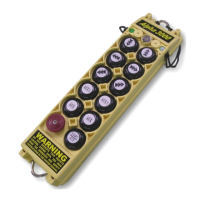
Note A: AU & AD output contacts represent the 7
th
and 8
th
pushbuttons on the transmitter (AUX↑
& AUX↓), which can be used for the auxiliary hoist motion or other types of applications
(refer to section 6.6 on page 24).
Note B: X & Y output contacts represent the 9
th
and 10
th
pushbuttons on the transmitter (AUX),
which can be used for the auxiliary trolley motion or other types of applications (refer to
section 6.6 on page 24). X1 represents 1-speed, X2 represents 2-speed, X3 represents
3-speed; Y1 represents 1-speed, Y2 represents 2-speed, Y3 represents 3-speed.
Note C: AUX output contact represents the 11
th
pushbutton on the transmitter (START/AUX),
which can be used for lights, horn, or other types of applications (refer to section 6.6 on
page 24).
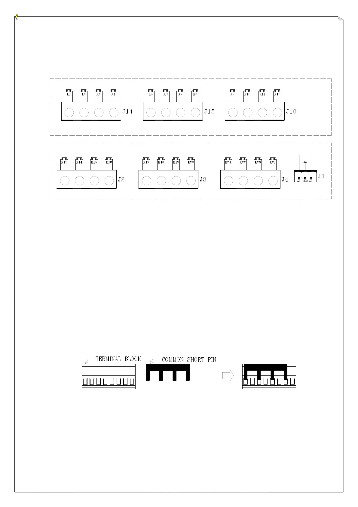
Terminal Block and Common Shorting Pin Assembly
Common shorting pin illustrated above can be used rather than “daisy chaining” wiring for the
common.



 To Next Page