4
4
.
.
2
2
A
A
l
l
p
p
h
h
a
a
3
3
0
0
0
0
0
0
F
F
M
M
o
o
d
d
e
e
l
l
s
s
I
I
n
n
t
t
e
e
r
r
n
n
a
a
l
l
A
A
s
s
s
s
e
e
m
m
b
b
l
l
y
y
11
~
7
12
13
14
15
16
6
5
4
K1
K2
K3
K4
K5
K6
K7
K8 K9
K10 K11 K12
K24
K23
K22K21
~
1
2
3
8
9
10
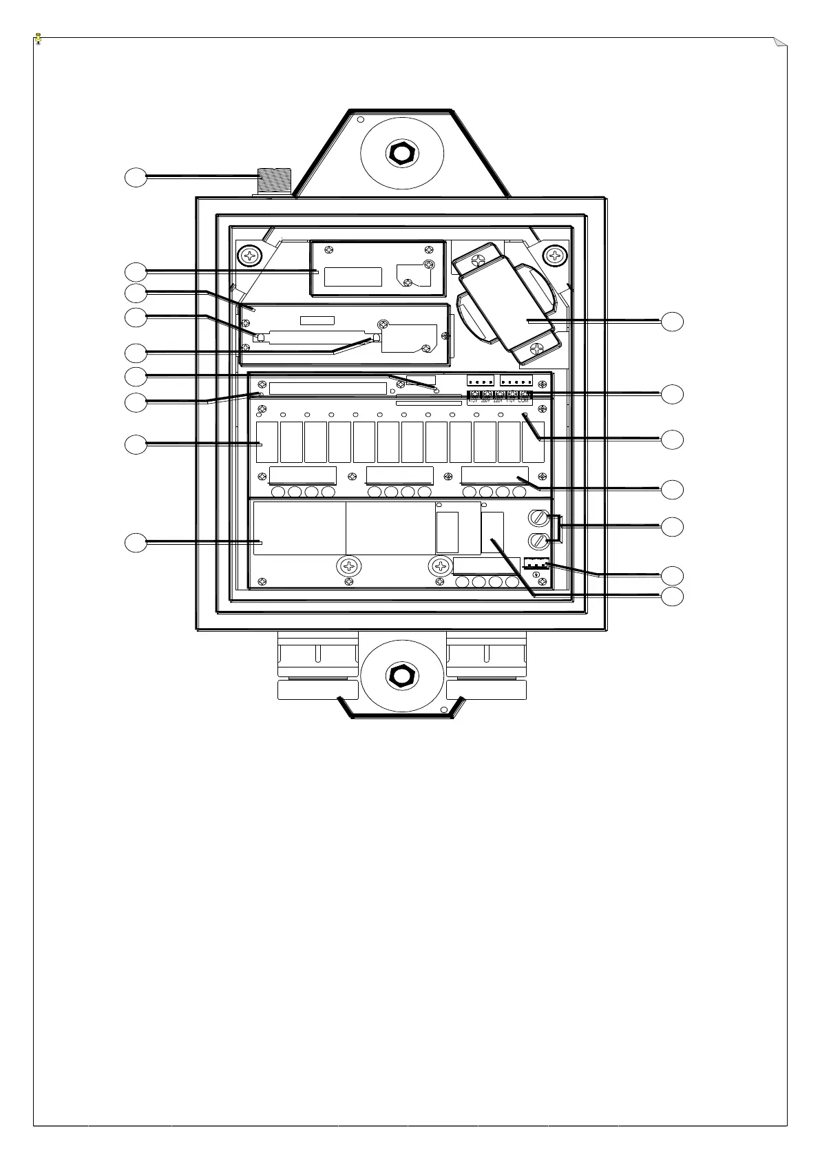
(Alpha 3000F2 & F3 Models Receiver Internal View)
1. Antenna Seat 9. Bottom Relay Board
2. Receiving RF Module 10. Power Transformer
3. Decoder Module 11. Input Voltage Selector Seat
4. Decoder Module Power Display 12. Contact Relay LED Display
5. Receiver Status LED Display* 13. Terminal Block
6. SQ Status LED Display* 14. Power Fuses (1.0A)
7. Power (AC) LED Display 15. AC Power Input
8. Upper Relay Board 16. MAIN Contact Relay
* Please refer to page 27 for Receiver and SQ display information