0 1 1 0 0 11 0
Soldered ----- ' I ' Value
Not Soldered ----- ' O ' Value
6
6
.
.
2
2
S
S
e
e
c
c
u
u
r
r
i
i
t
t
y
y
I
I
D
D
C
C
o
o
d
d
e
e
S
S
e
e
t
t
t
t
i
i
n
n
g
g
s
s
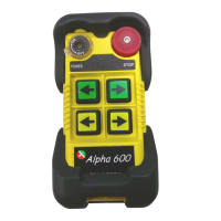
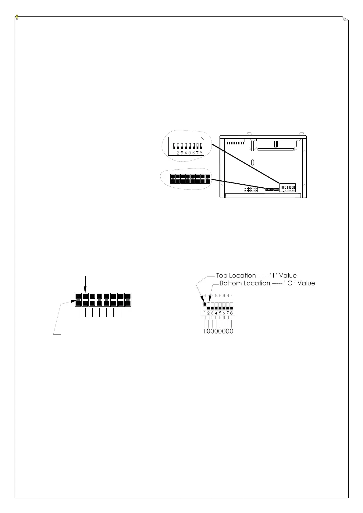
Transmitter ID code can be readjusted via an 8-position soldering slot (the first 8 digits of the ID code)
and an 8-position dip-switch (the last 8 digits of the ID code). Please refer to page 5 and page 7 for the
location of the soldering slot and dip-switch on the encoder board. As for the receiver ID code setting,
the soldering slot and the dip-switch are located inside the decoder module; please refer to page 9 & 10
and below illustration.
(Decoder module internal view)
Please note the first 8-digit of the ID code can be changed or altered simply by soldering the two
contact points together (“1” value); the position is at “0” value when unsoldered (two points open).
The last 8-digit ID code is set via an 8-position dip-switch located next to the 8-position soldering slot.
Due to Alpha 3000 series’ ID code (or address code) is 16-digit long, the first 8 digits are set via the
soldering slot and the remaining last 8 digits are set via the dip-switch (total of 16 digits). For the
soldering slot, the “SH8” represents the 1
st
digit of the ID code and “SH15” represents the 8
th
digit of
the ID code. As for the dip-switch, the “1” represents 9
th
digit of the ID code and the “8” represents the
16
th
digit of the ID code (last digit). Next page are some sample illustrations for better understanding
on how to set the entire 16-digit ID code via the soldering slot and the dip-switch.