3
3
.
.
2
2
A
A
l
l
p
p
h
h
a
a
3
3
0
0
0
0
0
0
F
F
M
M
o
o
d
d
e
e
l
l
s
s
I
I
n
n
t
t
e
e
r
r
n
n
a
a
l
l
A
A
s
s
s
s
e
e
m
m
b
b
l
l
y
y
6
7
11
1
4
3
2
9
1
2
3
4
5
6
7
8
8
5
10
1 2 3 4
5
6
7
8
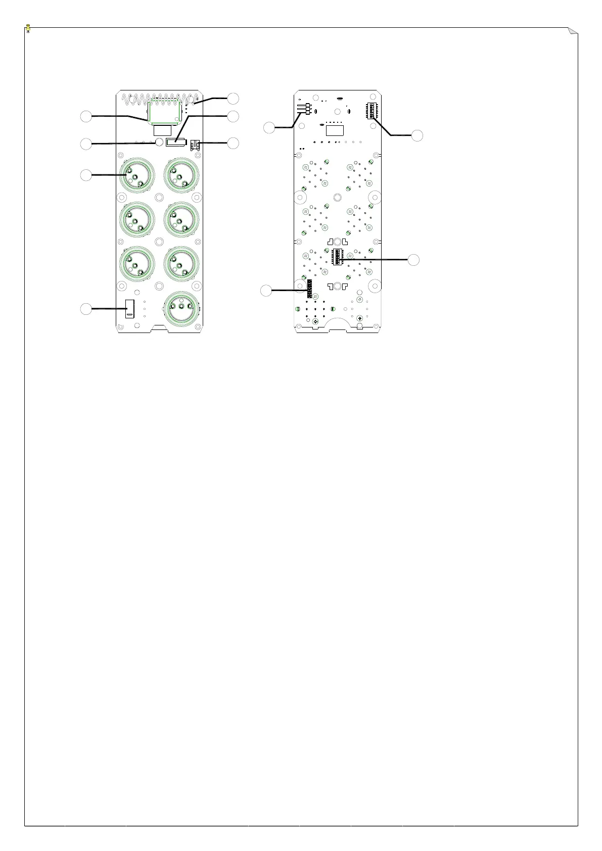
(PCB Front View) (PCB Back View)
1. RF module 6. Power ON/OFF Micro-Switch
2. Status LED Display 7. Battery Power Connector
3. 1, 2 or 3-Step Pushbuttons 8. RF test pin
4. Emergency Stop Button (EMS) 9. ID Code Soldering Slot (1
st
~ 8
th
digit)
5. Internal Antenna 10. Channel Dip-switch
11. ID Code Dip-switch (9
th
~16
th
digit)