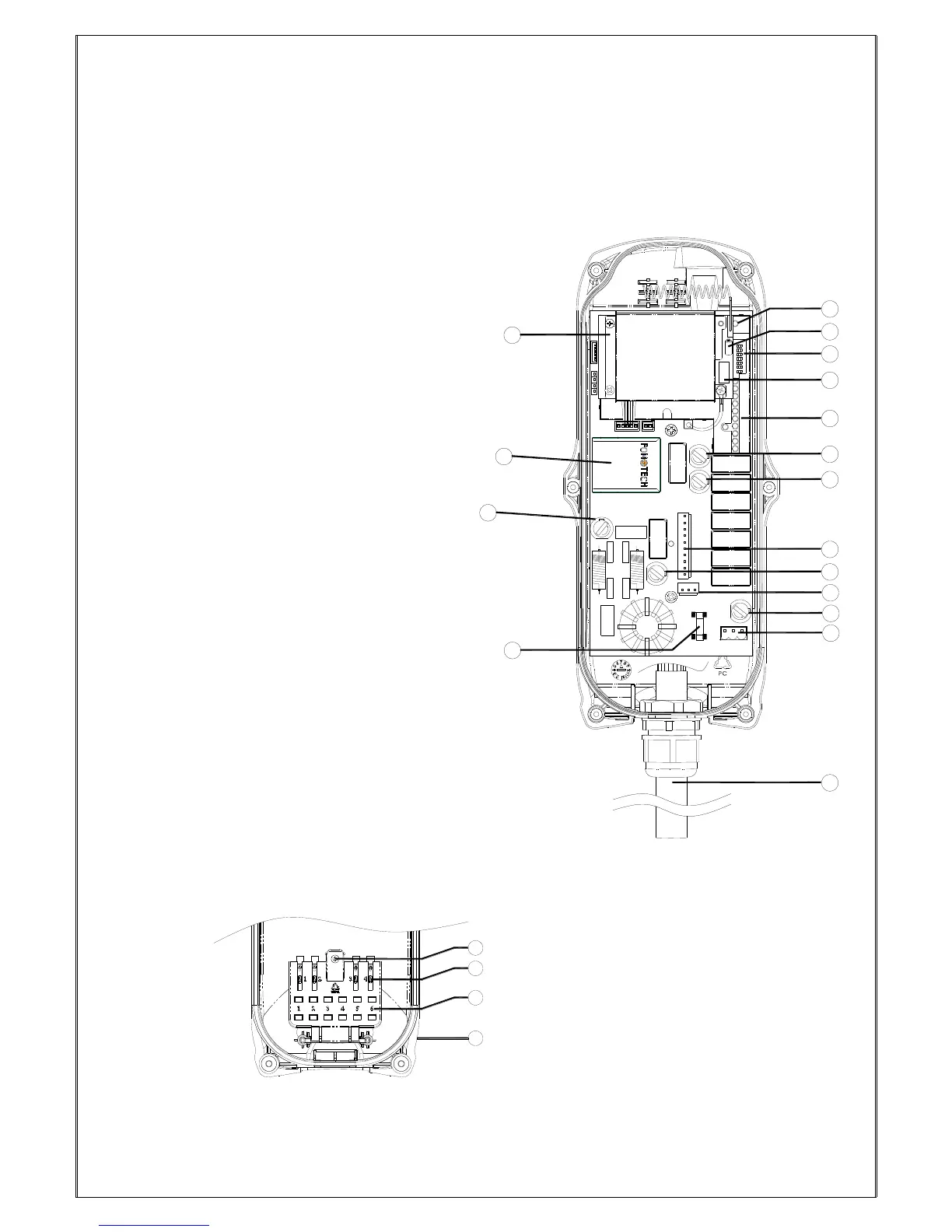
(Fig. 7) Internal Parts Assembly
1) Receiving RF module
2) Power module *
3) Secondary power AC fuse (F1)
4) Primary power AC fuse (FF1)
5) System status LED display*
6) External antenna port
7) ID code dip-switch
8) RF channel dip-switch
9) Contact relay LED display
10) Pushbutton #1 and #2 fuse (5.0A)
11) MAIN fuse (5.0A)
12 Contact output seat (CN3)
13) Low-voltage (LV) fuse (5.0A)
14) Contact output seat (CN4)
15) Pushbutton #3 and #4 fuse (5.0A)
16) AC power input seat (CN2)
17) Cable gland & output cable
* Power module: Including transformer or
full-voltage module.
* Please refer to 4.3 α604/α608/α612 Receiver
Power Fuse List.
*Please refer to page 36 for system status
LED display information.
1) Spare fuse & jumper compartment
2) Spare Jumper slots
3) Spare fuse slots
4) Receiver top casing