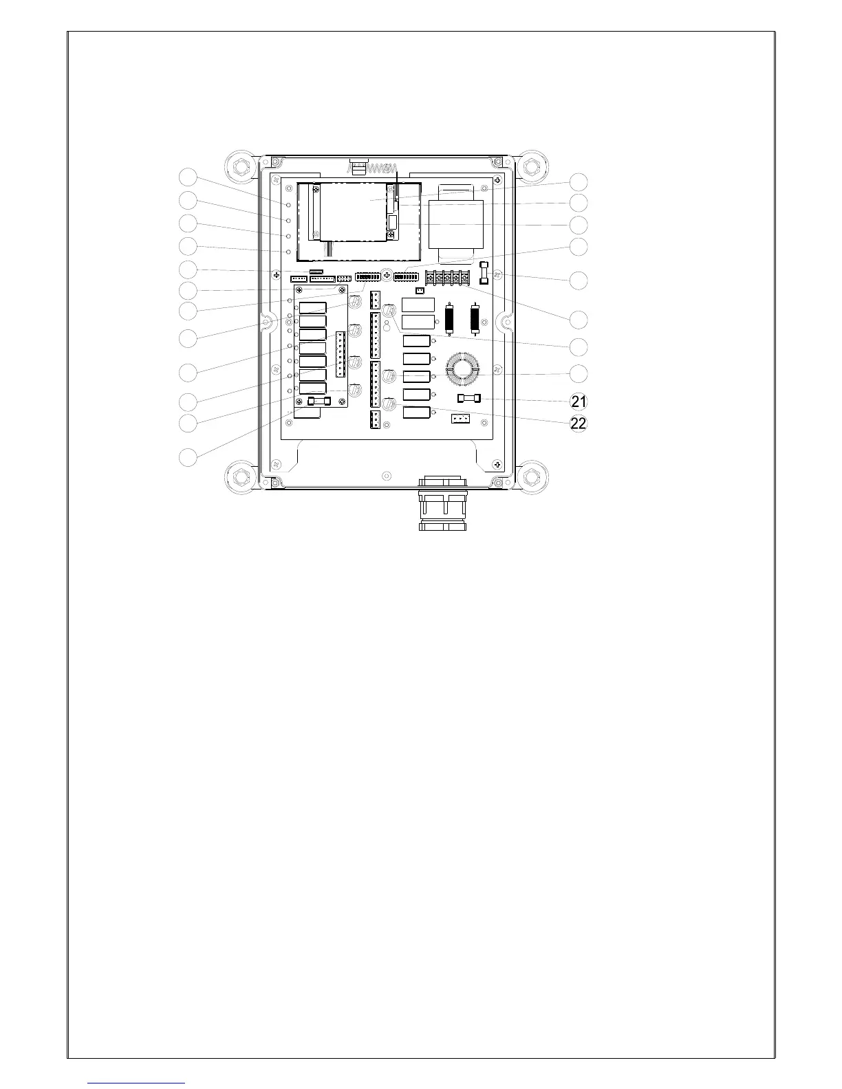
(Fig. 10) Internal Parts Assembly
1) Power LED display* 12) Pushbutton #1 and #2 relay fuse (5.0A)
2) SQ LED display** 13) Receiving RF module or PLL (Phase Lock Loop)
3) Status LED display**** 14) External antenna port
4) DC power relay LED display*** 15) RF channel dip-switch
5) Programming port 16) ID code dip-switch
6) Jumper settings 17) Secondary power fuse (0.8A) (except for AC48V)
7) Function dip-switch 18) Voltage selector seat
8) Pushbutton #3 and #4 relay fuse (5.0A) 19) MAIN relay fuse (5.0A)
9) Pushbutton #5 and #6 relay fuse (5.0A) 20) Pushbutton A4 relay fuse (5.0A)
10) Pushbutton A1and A2 relay fuse (5.0A) 21) Primary power fuse (1.0A) (AC110V up only)
11) Pushbutton A3 relay fuse (5.0A) 22) Low-voltage (LV) relay fuse (5.0A)
* POWER ~ AC Power Source Indicator "on" → AC input power supplied.
"off" → No AC input power.
** SQ ~ RF Signal Indicator "on" → RF signal detected and received.
"off" → No RF signal detected or received.
Blinking at transmitter power “off” → Other radio interference.
*** RELAY_COM ~ DC Power Source to Relays "on" → DC power to relays.
"off" → No DC power to relays.
**** STATUS ~ Receiver System Status LED Display → Please refer to page 36.