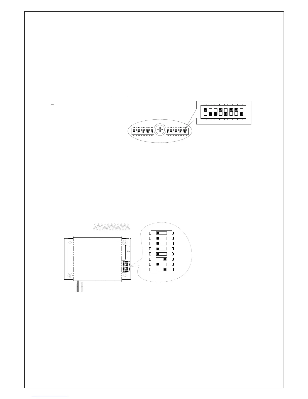
Please refer to Fig. 18 Internal Parts Assembly (Page 11) for 8-position ID code dip-switch to set receiver ID
code.
Top slot “1”; bottom slot “0”
Set the ID codes needed on the decoder board dip-switch.
For example: the ID codes → 10010110
(“1” value adds up must to be “4”)
7.2 Receiver RF Channel Settings
There are 68 sets of user-adjustable receiving RF channels that can be set manually via an 8-position
dip-switch located to the right of the receiving RF module. Change the receiving RF channel simply by
resetting the 8-position dip-switch. For the location of the receiving RF module, please refer to fig. 7, 8, and
10 on page 9, 10, and 12.
Top slot “1”; bottom slot “0”
For example:the channel dip-switch set above 00101, channel 05.