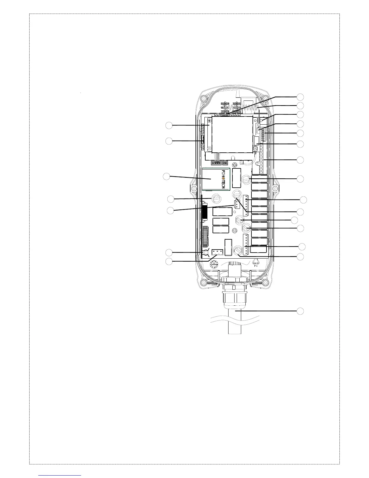
1) Receiving RF module
2) External programming port(CN5)****
3) Power module
4) Secondary power AC fuse (F1)**
5) Contact output seat (CN8)
6) Primary power AC fuse (FF1) **
7) AC power input seat (CN2)
8) External programming port(CN9)****
9) Internal Antenna
10) System Status LED display***
11) External antenna port
12) ID code dip-switch
13) RF channel dip-switch
14) Contact relay LED display
15) Pushbutton #1and #2 fuse (5.0A)
16) Contact output seat (CN3)
17) MAIN contact fuse (5.0A)
18) Pushbutton #3 and #4 fuse (5.0A)
19) Pushbutton #5 and #6 fuse (5.0A)
20) Contact output seat (CN4)
21) LV & AUX fuse (5.0A)
22) Cable gland & output cable
* Power module: Including transformer or
full-voltage module.
** Please refer to 4.3 α604/α608/α612
Receiver Power Fuse List on Page 12.
*** Please refer to page 40 for system status
LED display information.
**** For item 2 & 8, the receiver and country
code / ID have to be set at the same time.
 Loading...