16
19
18
17
15
5
11
12
10
8
9
7
1
3
4
2
14
6
13
4
4
.
.
2
2
.
.
2
2
A
A
l
l
p
p
h
h
a
a
6
6
1
1
2
2
I
I
n
n
t
t
e
e
r
r
n
n
a
a
l
l
A
A
s
s
s
s
e
e
m
m
b
b
l
l
y
y
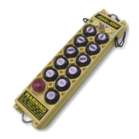
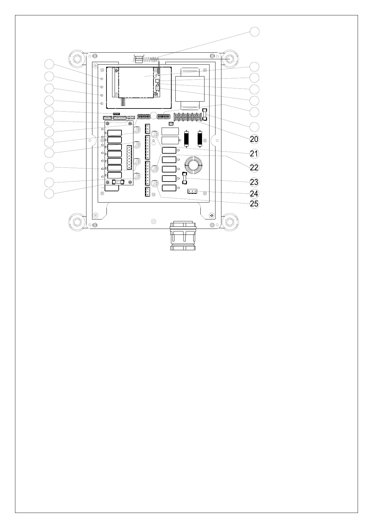
(Fig. 10) Internal Parts Assembly
DC power relay LED display***
Receiving RF module red status light
Transmitter pairing button
Secondary power fuse F1*(refer to power fuse list 4.3)
Pushbutton #3 and #4 relay fuse (5.0A)
Pushbutton #5 and #6 relay fuse (5.0A)
Pushbutton A1and A2 relay fuse (5.0A)
Pushbutton A4 relay fuse (5.0A)
Pushbutton A3 relay fuse (5.0A)
Primary power fuse FF1*(refer to power fuse list 4.3)
Pushbutton #1 and #2 relay fuse (5.0A)
Low-voltage (LV) relay fuse (5A)
* POWER ~ AC Power Source Indicator "on" → AC input power supplied.
"off" → No AC input power.
** SQ ~ RF Signal Indicator "on" → RF signal detected and received.
"off" → No RF signal detected or received.
Blinking at transmitter power “off” → Other radio interference.
*** RELAY_COM ~ DC Power Source to Relays "on" → DC power to relays.
"off" → No DC power to relays.
**** STATUS ~ Receiver System Status LED Display → Please refer to page 39.