4
4
.
.
R
R
E
E
C
C
E
E
I
I
V
V
E
E
R
R
O
O
U
U
T
T
L
L
I
I
N
N
E
E
4
4
.
.
1
1
A
A
l
l
p
p
h
h
a
a
6
6
0
0
4
4
~
~
6
6
0
0
8
8
4
4
.
.
1
1
.
.
1
1
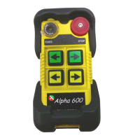
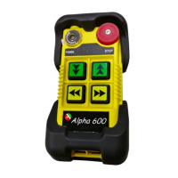
A
A
l
l
p
p
h
h
a
a
6
6
0
0
4
4
~
~
6
6
0
0
8
8
M
M
o
o
d
d
e
e
l
l
s
s
E
E
x
x
t
t
e
e
r
r
n
n
a
a
l
l
A
A
s
s
s
s
e
e
m
m
b
b
l
l
y
y
SIZE:310mm X 134mm X 72mm
AC
SQ
M
A
W
S
N
E
U
D
AC
SQ
M
A
VOLT:
CH:
MOD:
S/ N:
FREQ:
ID:
FILTER
Anti-vibration spring
must be grounded
POWER
MAIN
F6
5A
F1
F5 5A
LV/AUX1
COM4
17
L2(X2)
L1(X1)
GRN/YEL
COM5
MAIN
22
FF1
21
20
18
19
AUX1
AUX2
NC
COM3
NC
COM2
15
16
14 LV
N1
S1
COM1
D1
W1
E1
NC
NC
U1
F4 5A
F3 5A
13
10
11
12
9
8
3
5
6
7
4
F2 5A
2
1
BRIDGE
TROLLEY
HOIST
/AUX2
60947 EMS
EN ISO 13849-1:2008, PLd
1
2
3
7
8
9
4
5
6
11
10
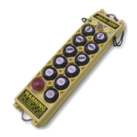
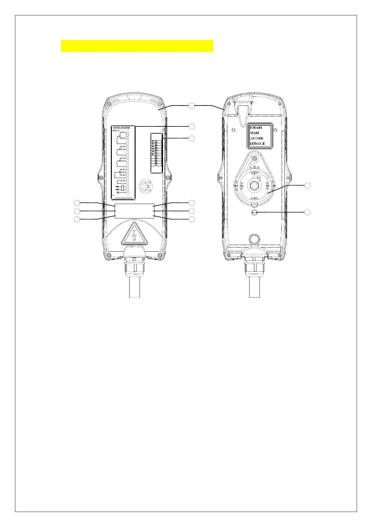
(Fig.5) Front View (Fig.6) Back View
1) Receiver enclosure 5) System frequency 9) System serial number
2) Wiring diagram 6) Supplied voltage 10) Anti-vibration spring
3) Receiver LED displays* 7) System ID code 11) Grounding (GND)
4) Type model 8) System RF channel
* A ~ AUX Relay Contact Indicator (for Alpha 607A /608B models only).
* M ~ MAIN and 2
nd
Speed Relay Contact Indicator.
Green "on" → MAIN activated (All models).
Red "on" → 2
nd
speed activated (for Alpha 608B model only).
* SQ ~ RF Signal Indicator (Red).
"on" → RF signal detected and received.
"off" → No RF signal detected or received.
Blinking at transmitter power "off" → Other radio interference.
* AC ~ Power Source Indicator (red) "on" → AC input power supplied.
"off" → No AC input power.