16
2
16
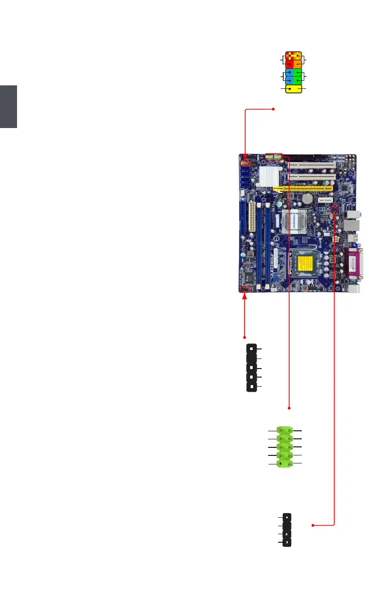
Front Panel Connector : FP1
This motherboard includes one connector for connecting
the front panel switch and LED Indicators.
Hard Disk LED Connector (HDD-LED)
Connect to the chassis front panel IDE indicator LED.
It indicates the active status of the hard disks. This
2-pin connector is directional with +/- sign.
Reset Switch (RESET-SW)
Attach the connector to the Reset switch on the front
panel of the case; the system will restart when the
switch is pressed.
Power LED Connector (PWR-LED)
Connect to the power LED indicator on the front panel
of the chassis. The Power LED indicates the system’s
status. When the system is in operation (S0 status),
the LED is on. When the system gets into sleep mode
(S1) , the LED is blinking; When the system is in S3/
S4 sleep state or power off mode (S5), the LED is off.
This 2-pin connector is directional with +/- sign.
Power Switch Connector (PWR-SW)
Connect to the power button on the front panel of
the chassis. Push this switch allows the system to
be turned on and off rather than using the power
supply button.
IR/CIR Connector : IR/CIR
This connector supports infrared wireless transmitting
and receiving device.
USB Connectors : F_USB1/2
In addition to the four USB ports on the rear panel, this
product also provides two 10-pin USB headers on its
motherboard. By connecting through USB cables with
them, user can quickly expand another four USB ports
on the front panel.
Speaker Connector : SPEAKER
The speaker connector is used to connect speaker of
the chassis.
EMPTY
HDD-LED
RESET-SW
NC
+
-
PWR-SW
+
-
PWR-LED
1
2
10
9
FP1
NC
SPKJ
EMPTY
SPEAKER
SPKJ
1
2
3
4
1
2
3
4
5
+5V
EMPTY
IRRX
GND
IRTX
IR/CIR
NC
GND
VCC
D+
D-
D+
GND
D-
VCC
EMPTY
1
2
10
9
F_USB 1/2

 Loading...