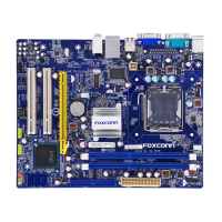
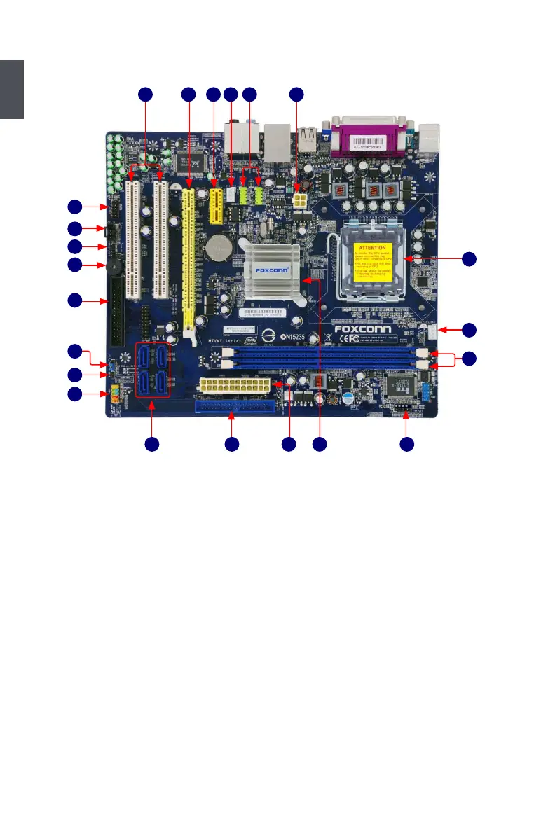
1-2 Layout
Note : The above motherboard layout is for reference only, please refer to the physical
motherboard for detail.
1. 4-pin ATX 12V Power Connector
2. Front USB Connectors
3. SYS_FAN Header
4. PCI Express x1 Slot
5. PCI Express x16 Slot
6. PCI Slots
7. Front Audio Connector
8. CD_IN Connector
9. S/PDIF_OUT Connector
10. Bu��er (or Speaker Connector)
11. Floppy Connector
12. Clear CMOS Jumper
13. Chassis Intrusion Alarm Header
14. Front Panel Connector
15. SATA Connectors
16. IDE Connector
17. 24-pin ATX Power Connector
18. Chipset: NVIDIA GeForce 7050 /
nForce 610i
19. IrDA Connector
20. DDR2 DIMM Slots
21. CPU_FAN Header
22. LGA 775 CPU Socket
8
9
12
13
14
7
11
10
1
2
45
6
21
20
22
1715 16 18 19
3
 Loading...