14
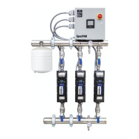
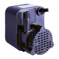
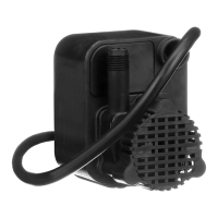
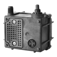
Inline Pressure Boosting System
Re-calibration of Control Head:
There are times , especially after servicing, that the Inline 400 needs to be re-calibrated.
This is necessary in order to re-establish a reference point for the indication of ow. Follow
these procedures for Field Flow Calibration:
1. Before powering the unit on, verify there is no water owing in the system. This will
ensure that the ow piston is in the fully seated (zero ow) position.
2. While holding down the push button on the status display, plug the units power
cord into the receptacle (or switch on breaker if hard-wired). Continue holding
down the button for ve seconds until both the green and red LEDs blink, indicating
calibration is complete. Release the button and the red LED should come on solid,
indicating calibration was successful.
3. Open valves/taps to begin water ow and conrm unit is operating properly.
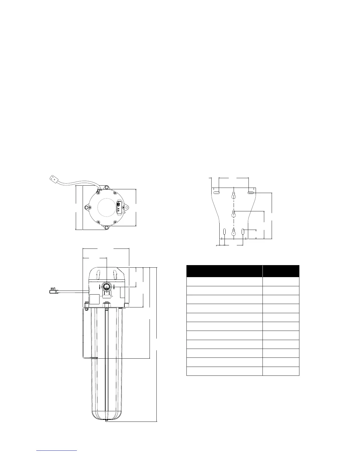
Outline Dimensions for Inline 400:
[225]
8,86
[135]
5,31
[45]
1,77
[35]
1,38
[146]
5,75
[90]
3,54
[25]
0,98
[180]
7,09
[216]
8,50
[117]
4,61
[225]
8,86
[95]
3,74
[194]
7,64
[444]
17,48
[752]
29,61
Model Description Order No.
Pump Housing Wrench 305572001
Inlet or Outlet Pressure Switch (40 psi) 305572007
Replacement Pump Housing 305572009
Replacement Control Cap w/display 305572010
Replacement Mounting Base 305572011
Motor Capacitor - 115 V (w/boot) 305572012
Motor Capacitor - 230 V (w/boot) 305572013
Power Cord - 115 V 305572014
Power Cord - 230 V 305572015
Flow Piston Kit 305572016
Pump Housing O-Ring 305572017