DFA400 Rev150730
20
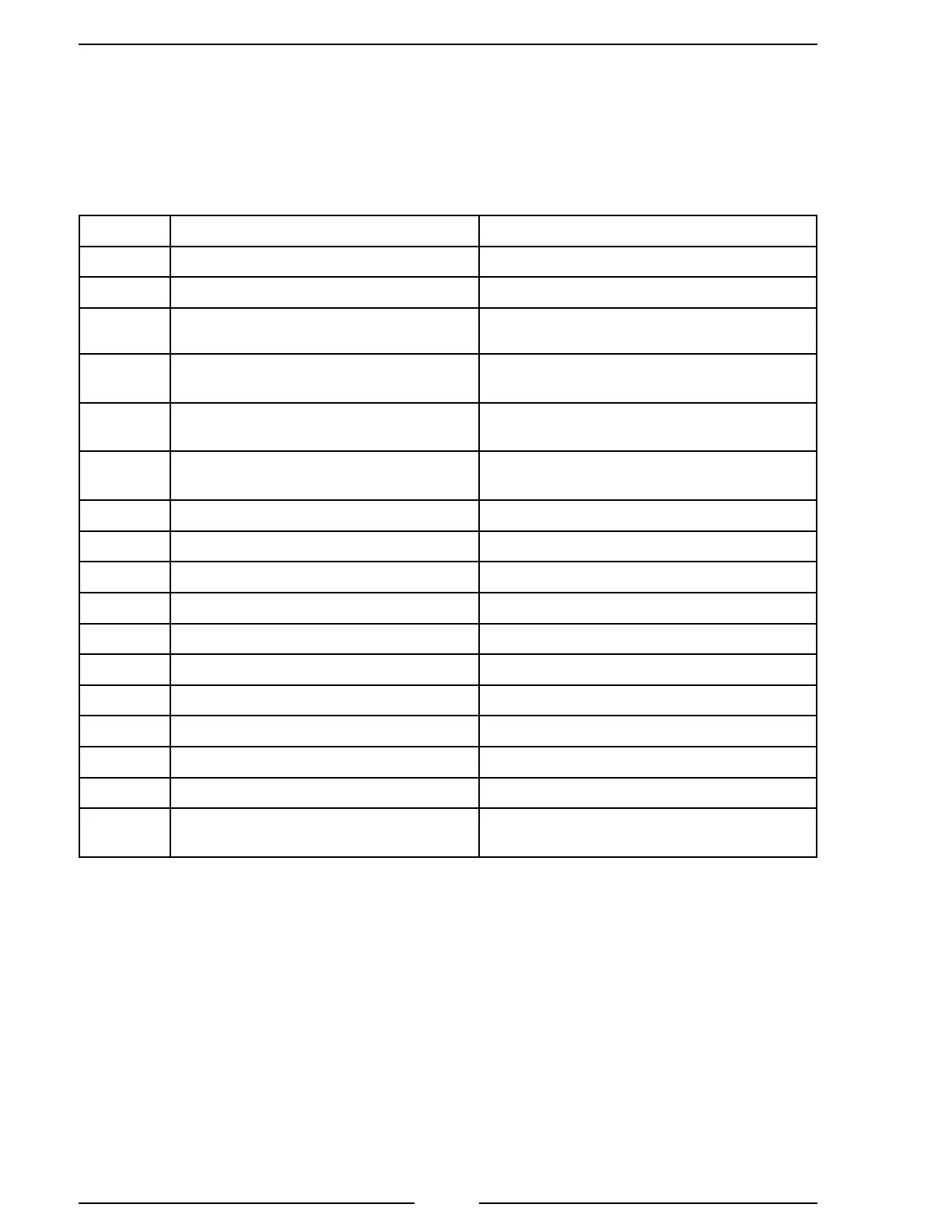
CODE FEATURE OPTION
311
Flow Rate Increment Set Point 0000 to 9999
312
ID Number 0 to 99
313
Module Function Pri, SLA, ACC, SU
(Refer to Note for ACC and SU)
315
High Flow Warning 0001 to 9999
0 = Disabled
316
Low Flow Warning 0001 to 9999
0 = Disabled
317
Totalizer Reset Yes = Resets to 0 at Power On
No = Stores Total Flow at Power Off
318*
Flow Cutoff (Frequency) 0 to 99.9 Hz
319*
Flow Cutoff (Flow Rate) 0 to 999
321
Flow Calibration (Single Point) 1 Calibration Point
322
Flow Calibration (Multiple Point) 9 Calibration Points
340
CAN Terminator On, Off
E202
Invalid Program Code Entered Re-Enter Code
E204
No Flow Sensor Signal Check Water Flow and Wiring
E206
Invalid Calibration Point Select Different Calibration Point
E208
Memory Failure Contact Factory
E210
Exceeded Maximum Calibration
Points
Exit Calibration Procedure
Table 1. Program Code Quick Reference
Notes:
- Refer to Program Code Descriptions for detailed information.
- The time-out feature returns the program to normal operation in ve
seconds if input is not detected.
- When a valid code has been entered and a programed value or option is
shown in the display, the time-out feature is disabled.
* Code 318 is valid when the code 319 is set to 0. When a value is set for
code 319, code 318 is ignored.