DFA400 Rev150730
15
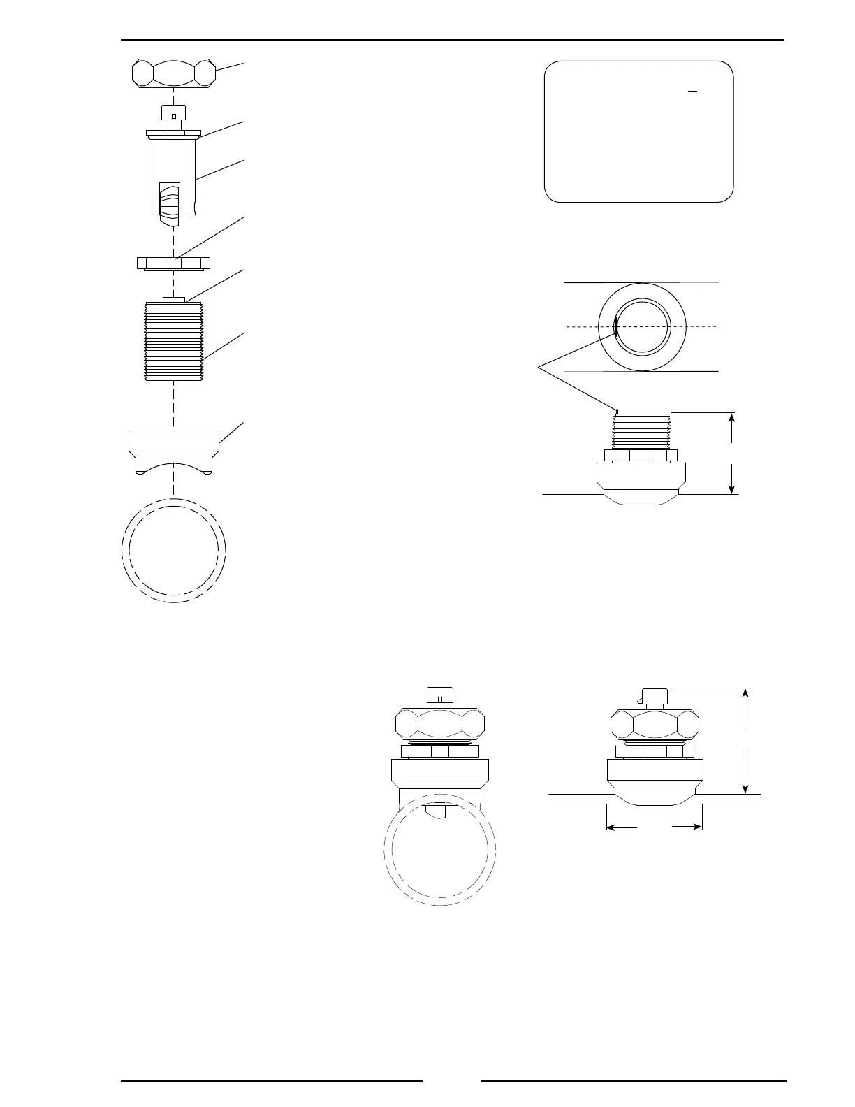
Figure 5. Weldment Installation
Pipe Size Dimension
(Sch 40) A
1.5 1.95 to 1.80
2 1.95 to 1.80
2.5 1.90 to 1.75
3 1.88 to 1.73
3.5 1.88 to 1.73
4 1.85 to 1.70
5 1.85 to 1.70
Measurements are in inches.
Note: When the retainer cap is
tightened make sure the ow
sensor engages the alignment
tab and does not rotate.
Note: Allow a minimum of 2 inches
clearance above the sensor for
connector removal/installation.
Make sure that the alignment tab is
centered on the pipe center line.
Note: Dimensions are
typical and are an aid to
determine ow sensor
mounting locations.
2.5"
2.8"
Retainer
Cap
Sensor
Housing
Weldment
O-Ring
Paddlewheel
Flow Sensor
Alignment
Tab
Tru-Seal
Locknut
Alignment
Tab
A
C
L