DFA400 Rev150730
28
WIRING
The following gures include wiring and cable information.
Display Module
A remote display module requires four (4) wires, power (pins 1 and 2) and the
datalink connection (pins 7 and 8) to the primary display. A remote display must be
programmed with the same ID number as the primary display.
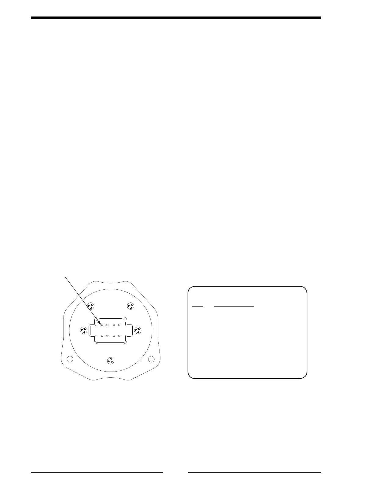
Figure 6. Display Module Wiring
8-Pin Connector/Cable
Pin Description
1 Power
2 Ground
3 Flow Sensor +5 VDC
4 Flow Sensor Ground
5 Flow Sensor Signal
6 NC
7 Proprietary Datalink (–)
8 Proprietary Datalink (+)
Rear View
Pin 1