FreeWave Technologies Spread Spectrum Transceiver User Manual
900 MHz and 2.4 GHz
V5.0S
48
RS232 Pin Assignments
Definitions:
Pin 1: Carrier Detect (CD) Used to show that there is an RF connection
between modems.
Pin 2: Transmit Data (TX) This is used to transmit data bits serially
from the modem to the system device
connected to the modem.
Pin 3: Receive Data (RX) This is used to receive data bits serially from
the system device to the modem device
connected to the modem.
Pin 4: Data Terminal Ready (DTR) The modem only uses this line in Point-to-
Point Slave/Master switchable mode (refer to
Operation Mode Selections) or for DTR
Connect (refer to Multipoint Operation).
Pin 5: Ground (GND) Signal return for all signal lines shared with
Pin 9.
Pin 6: Data Set Ready (DSR) Always high when the radio is powered from
the 2.5mm power connector. Indicated
power is on to the radio. Also, this pin can
be used for +12Volts when powering the
modem directly through the RS-232 port.
Note: This is not used on the OEM module.
Pin 7: Request to Send (RTS) The modem does not recognize RTS for flow
control. RTS is used as a control line in
RTS/CTS mode (refer to Radio
Transmission Parameters).
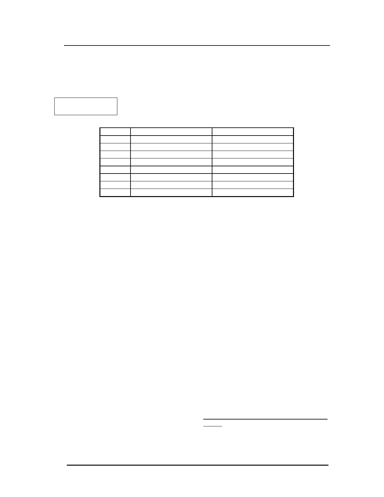
Table 17: RS232 Pin
Assignments
Pin Assignment Signal
1 Carrier Detect Output
2 Transmit Data Output
3 Receive Data Input
4 DTR Input
5 Ground
6 Data Set Ready Output
7 RTS Input
8 Clear to Send Output
9 Ground