Electrical System General
Information
The S2 Chassis uses an electrical system where
multiple electrical signals are carried along a simpli-
fied set of wires, reducing the size of wiring bundles.
There are significantly fewer wires overall, meaning
less chance of damage, shorts, and other problems.
The information in this chapter is to help familiarize
the driver with the basic electrical system. Servicing
the electrical system requires special skills and
equipment and should be performed only by a quali-
fied technician. Take the vehicle to an authorized
Freightliner service facility for repairs.
WARNING
Do not attempt to modify, add, splice, or remove
electrical wiring on this vehicle. Doing so could
damage the electrical system and result in a fire
that could cause serious personal injury or prop-
erty damage.
Power Distribution Modules
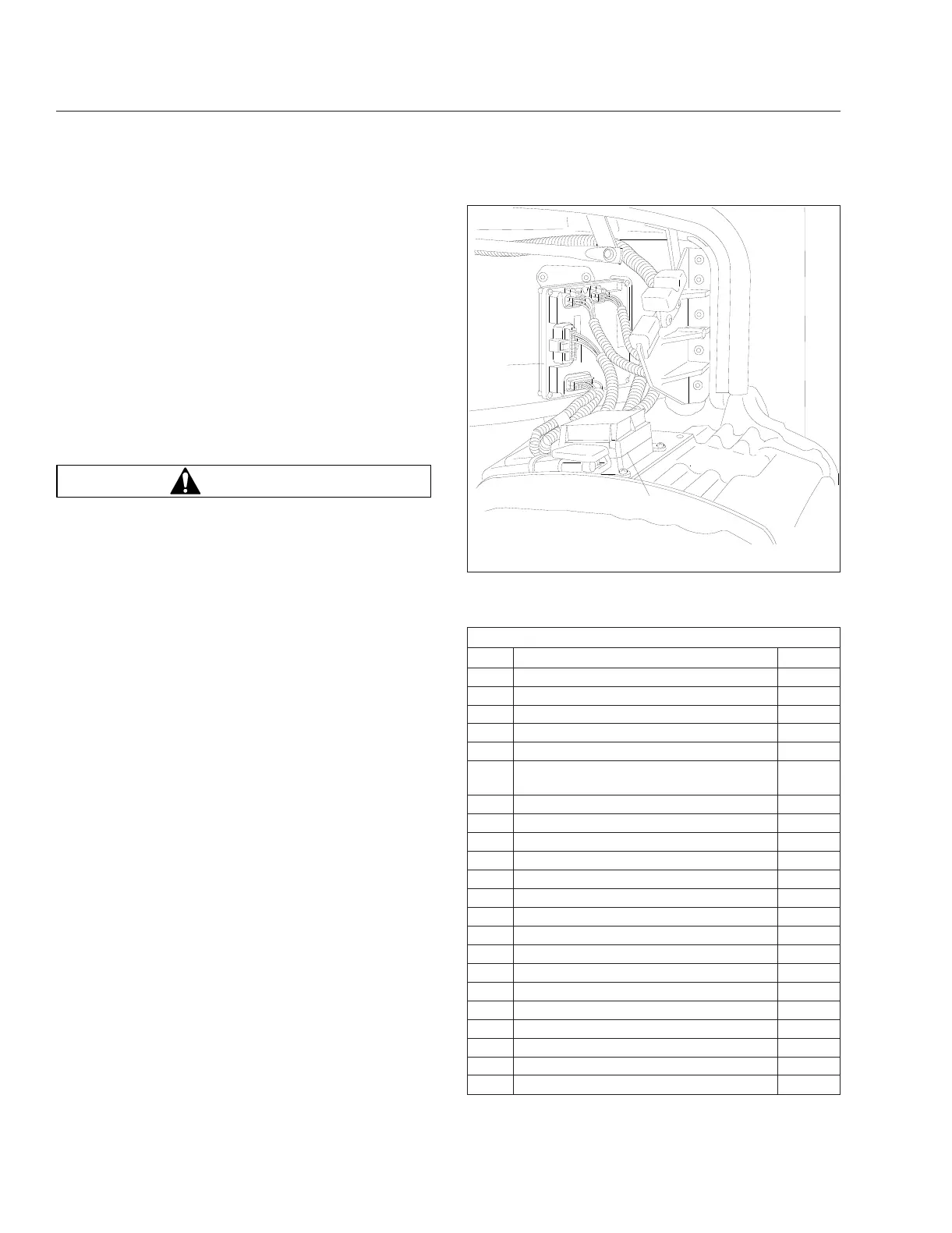
There are three electrical modules, a main power
distribution module (PDM) located under the hood on
the driver’s side above the fender, a chassis module
located between the frame rails, and a cab module
located to the left of the driver under the switch
panel.
The main PDM distributes battery power to the vehi-
cle’s control modules and contains the fuses required
to protect the power feed circuits to the control mod-
ules. See
Fig. 6.1. While the main PDM provides
power to the modules, the modules themselves con-
trol power flow and circuit protection to the various
components of the vehicle electrical systems. Be-
cause of this, traditional PDM devices such as relays
and circuit breakers are no longer necessary on the
main PDM.
Inside the lid of the fuse box there is a sticker that
shows the locations of the fuses and describes the
circuit(s) that each fuse protects. Fuse configuration
will vary depending on the PDM assembly installed.
See
Fig. 6.2. See Table 6.1 for descriptions of a
typical set of fuses.
Because the electrical system is multiplexed, no re-
lays are needed. The multiplexing module performs
the functions normally provided by relays.
Main PDM Fuse Identification
CAV Description Fuse
F1 Engine VCU (spare) 10A
F2 Blower Motor 30A
F3 Engine ECU 20A
F4 Spare 30A
F5 Ignition Switch 5A
F6 HydroMax RLY (if equipped with
hydraulic brakes)
30A
F7 Bulkhead Module 30A
F8 ICU3 10A
F9 Transmission ECU 10A
F10 Spare —
F11 Spare —
F12 Radio/Diagnostic 20A
F13 Chassis Module 30A
F14 Spare —
F15 Bulkhead Module 30A
F16 ABS ECU 25A
F17 Chassis Module 30A
F18 Bulkhead Module 30A
F19 Chassis Module 30A
F20 Bulkhead Module 30A
F21 Spare —
F22 Bulkhead Module 30A
09/25/2001
f543935
1
2
1. Bulkhead Module 2. Main PDM
Fig. 6.1, Location of the Main PDM (under driver side
hood, above fender)
Electrical Systems
6.1