070.610-IOM (JUL 21)
Page 17
RWF II Rotary Screw Compressor Units
Installation
Wire sizing
Control power supply wires should be sized one size larger
than required for amperage draw to reduce instantaneous
voltage dips caused by large loads such as heaters, con-
tactors, and solenoids. These sudden dips in voltage can
cause the electronic control panel, whether it is a micro-
processor, a computer, or a PLC, to malfunction momen-
tarily or cause a complete reset of the control system. If
the wire is loaded to its maximum capacity, the voltage
dips are much larger, and the potential of a malfunction is
very high. If the wire is sized one size larger than required,
the voltage dips are smaller than in a fully loaded sup-
ply wire and the potential for malfunction is much lower.
The NEC code book calls for specic wire sizes to be
used based on current draw. An example of this would be
to use #14 gauge wire for circuits up to 15 amps or #12
gauge wire for circuits of up to 20 amps. As a result, when
connecting the power feed circuit to an electronic control
panel, use #12 gauge wire for a maximum current draw of
15 amp and #10 wire for a maximum current draw of 20
amp. Use this rule of thumb to minimize voltage dips at
the electronic control panel.
Voltage source
Selecting the voltage source is extremely important for
proper operation of electronic equipment in an industrial
environment. Standard procedure for electronic instru-
mentation is to provide a clean, isolated, separate-source
voltage in order to prevent EMI (from other equipment
in the plant) from interfering with the operation of the
electronic equipment. Connecting electronic equipment
to a breaker panel (also known as lighting panels or utility
panels) subjects the electronic equipment to noise gener-
ated by other devices connected to the breaker panel.
This noise is known as electromagnetic interference (EMI).
EMI ows on the wires that are common to a circuit. EMI
cannot travel easily through transformers and therefore
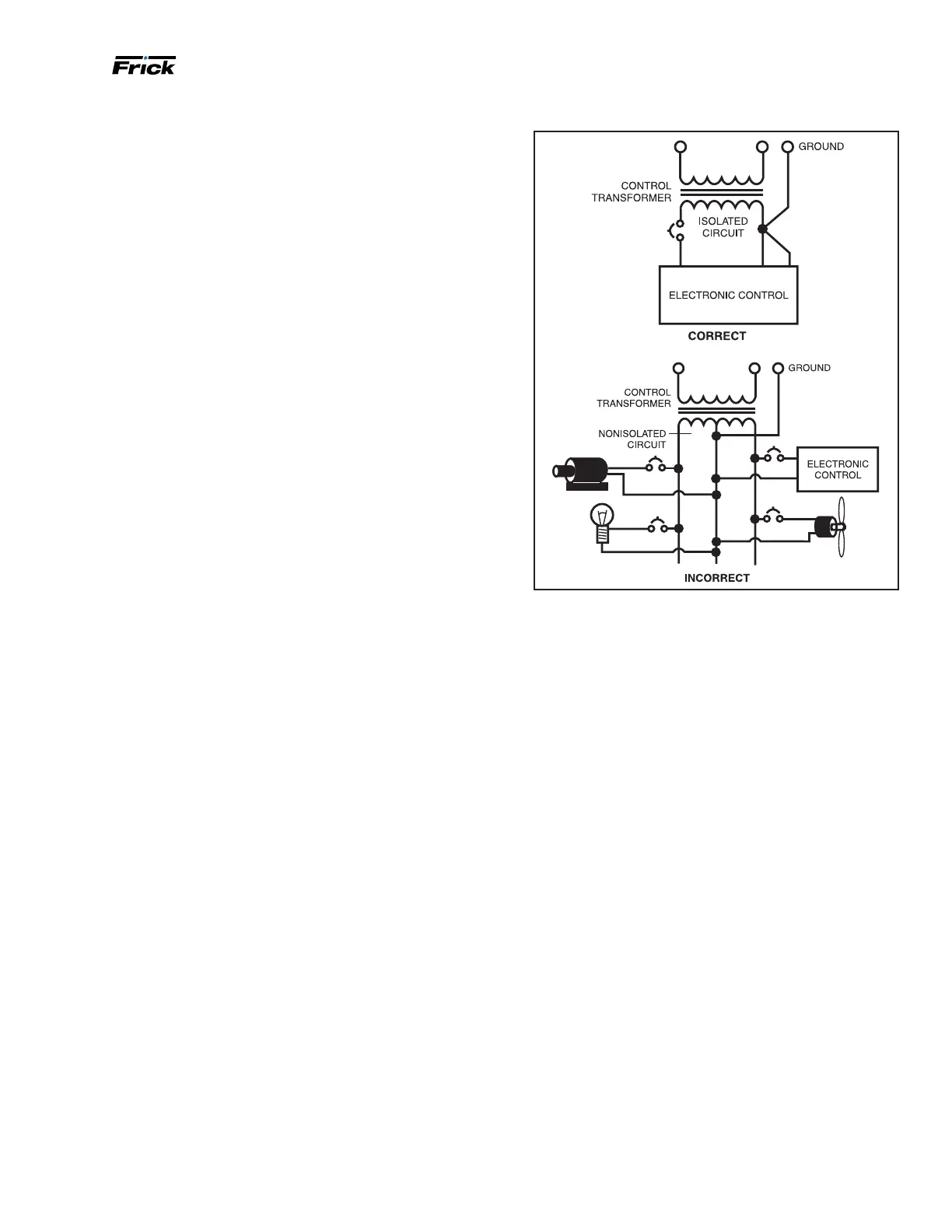
can be isolated from selected circuits. Use a control power
transformer of the proper VA rating, usually provided in
the compressor drive motor starter, to isolate the elec-
tronic control panel from other equipment in the plant that
generate EMI. See the following Figure.
Figure 20: Voltage source circuit to prevent EMI
Grounding
Grounding is the most important factor for successful
operation and is typically the most overlooked. The NEC
states that control equipment can be grounded by us-
ing the rigid conduit as a conductor. This worked for the
earlier relay systems, but it is in no way acceptable for
electronic control equipment. Conduit is made of steel and
is a poor conductor relative to an insulated stranded cop-
per wire. Electronic equipment reacts to very small cur-
rents and must have a proper ground in order to operate
properly; therefore, stranded copper grounds are required
for proper operation.
For proper operation, the control power ground circuit
must be a single continuous circuit of the proper sized
insulated stranded conductor, from the electronic control
panel to the plant supply transformer. See Figure 21. Driv-
ing a ground stake at the electronic control may also cause
additional problems since other equipment in the plant on
the same circuits may ground themselves to the ground
stake causing large ground ow at the electronic control
panel. Also, running multiple ground conductors into the
electronic control panel from various locations can create
multiple potentials resulting in ground loop currents. A
single ground wire (10 AWG or 8 AWG) from the electronic
control panel, that is bonded to the control power neutral
at the secondary side of the control power transformer
in the starter and then to the three-phase ground point,
yields the best results.

 Loading...