070.610-IOM (JUL 21)
Page 38
RWF II Rotary Screw Compressor Units
Maintenance
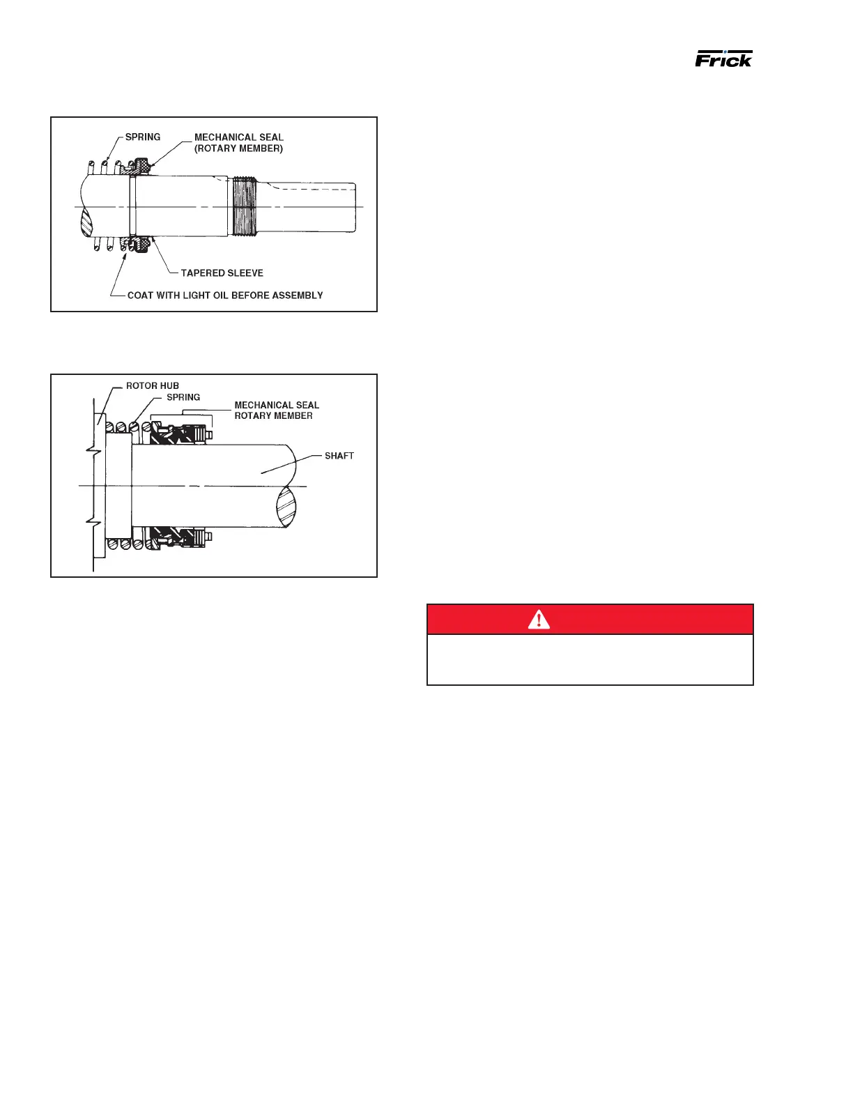
Figure 43: Shaft with sleeve
5. Place seal spring on shaft against rotor hub. See fol-
lowing Figure.
Figure 44: Shaft with seal spring
6. Slide rotary member, with lapped contact surface
facing away from spring, over installation sleeve on shaft
until just con tacting the spring. Do not compress spring.
Remove installa tion sleeve.
7. Coat rotor shaft with refrigeration oil. Install shaft
slowly pushing until the ends of rotor teeth are just below
the face of the casing.
8. Leave the rotor in this position. Withdrawal of rotor
and shaft may displace the carbon seal rotating face and
result in damage to the seal.
9. Place O-ring gasket on head and install head and idler
assembly on pump. Pump head and casing were marked
before disassembly to ensure proper reassembly. If not, be
sure idler pin, which is offset in pump head, is positioned
up and equal distance between port connections to allow
for proper ow of liquid through pump.
10. Tighten head capscrews evenly
1
1. Pack inner ball bearing with multipurpose grease, NLGI
#2.
GG, HJ, HL: Install bearing in casing with sealed side to-
wards head end of pump. Drive the bearing into the bore.
Tap the inner race with a brass bar and lead hammer to
position bearing. Install inner snap ring.
AS, AK, AL: Install bearing retainer washer over the shaft
before installing ball bearing. Install ball bear ing in casing
with sealed side towards head end of pump. Drive the
bearing into the bore. Tap the inner race with a brass bar
and lead hammer to position bearing.
12. GG, HJ, HL: Install shaft snap ring in groove in the
shaft. See Figure 41.
AS, AK, AL: Install bearing spacer over shaft and against
single row ball bearing. See Figure 42.
13. Pack lubrication chamber between inner ball bear-
ing and double-row ball bearing in the thrust-bearing
assembly approximately one-half full of multipurpose
grease, NLGI #2. The thrust-bearing assembly will take the
remaining space. See Figure 41 and Figure 42.
14. Pack double-row ball bearing with multipurpose
grease, NLGI #2.
GG, HJ, HL: Install ball bearing into bearing housing with
shield side toward coupling end of shaft. See Figure 42.
Install snap ring into bearing hous ing to retain ball bearing.
This snap ring has a tapered edge to t tapered groove in
bearing housing. The tapered edge is located away from
ball bearing.
AS, AK, AL: Install ball bearing into bearing housing. In-
stall lip seal in bearing housing end cap. The lip should
face towards end of shaft. Put bearing spacer collar in lip
seal and install in bearing housing and tighten setscrews
se curely. See Figure 42.
15. Insert brass bar or hardwood through port opening
between rotor teeth to keep shaft from turning.
16. Start thrust-bearing assembly into casing. Turn by hand
until tight. This forces rotor against head. Replace and
tighten locknut or shaft.
17. Remove brass bar or hardwood from port opening.
18. Adjust pump end clearance.
DANGER
Before starting pump, ensure that all drive equipment
guards are in place. Failure to properly mount guards
may result in serious injury or death.
Thrust bearing adjustment
See Figure 41 and Figure 42. Loosen two screws in face of
thrust-bearing assembly. If shaft cannot be rotated freely,
turn thrust-bearing assembly counterclockwise until shaft
can be turned easily.
1. While turning rotor shaft, rotate thrust-bearing assem-
bly clockwise until noticeable drag occurs. This is zero end
clearance.
2. Mark position of bearing housing with respect to the
casing.
3. Rotate thrust-bearing assembly counterclockwise the
dis tance listed below as measured on outside of bearing
hous ing.
4. Tighten two setscrews in face of bearing housing after
adjust ment is made to secure thrust-bearing assembly
position.
For viscosities above 2500 SSU, add additional end clear-
ance (0.004 in. for GG, HJ and HL size pumps and 0.005 in.
for AS, AK and AL size pumps).

 Loading...