070.610-IOM (JUL 21)
Page 37
RWF II Rotary Screw Compressor Units
Maintenance
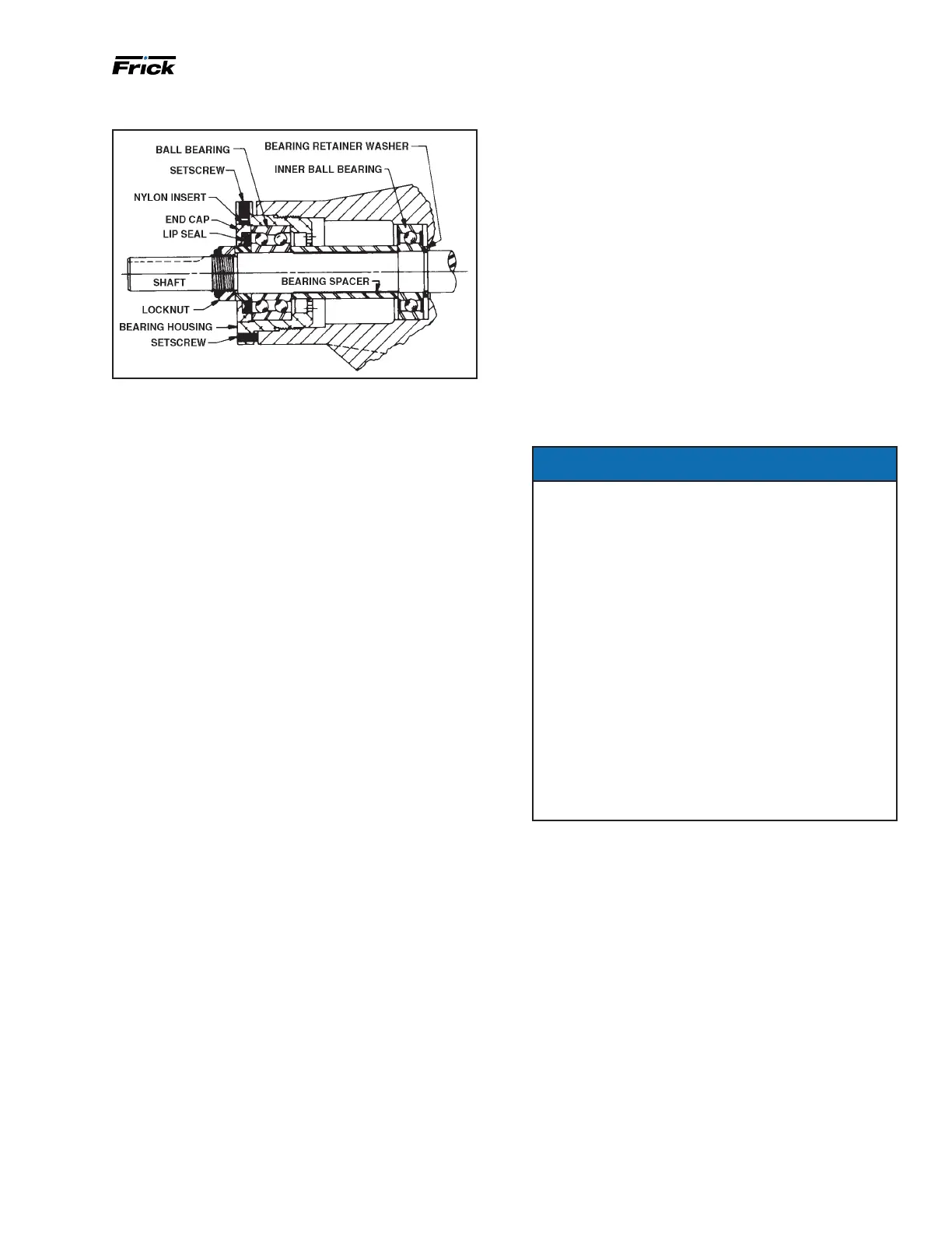
Figure 42: Thrust-bearing assembly (AS, AK, AL)
6. Loosen two setscrews in face of bearing housing and
turn thrust bearing assembly counterclockwise and remove
from casing. See Figure 41 or 30.
7. GG, HJ, HL: Remove snap ring from shaft. See Figure 41.
AS, AK, AL: Remove bearing spacer from shaft. See Figure
42.
8. Remove brass bar or piece of hardwood from port
opening.
9. The rotor and shaft can now be removed by tapping
on end of shaft with a lead hammer or, if using a regu-
lar hammer, use a piece of hardwood between shaft and
hammer.
The rotary member of the seal will come out with rotor
and shaft.
10. AS, AK, AL: Remove bearing retainer washer. The
washer may have stayed with rotor and shaft when re-
moved or is against ball bearing. See Figure 42.
11. Remove the mechanical seal rotary member and spring
from rotor and shaft assembly.
12. GG, HJ, HL: Remove inner snap ring and single-row
ball bearing from casing.
AS, AK, AL: Remove single-row ball bearing from casing.
13. Remove seal seat or stationary part of seal from cas-
ing.
14. Disassemble thrust-bearing assembly.
GG, HJ, HL: Remove outer snap ring from bearing hous ing
and remove ball bearing. See Figure 41.
AS, AK, AL: Loosen two set screws in ange outside di-
ameter. Rotate end cap and lip seal counterclockwise and
remove. Remove ball bearing. See Figure 42.
The casing should be examined for wear, particularly in
the area between ports. All parts should be checked for
wear before pump is put together.
When making major repairs, such as replacing a rotor and
shaft, it is advisable to also install a new mechanical seal,
head and idler pin, idler, and bushing. See Installing carbon
graphite bushings.
Clean all parts thoroughly and examine for wear or dam-
age. Check lip seals, ball bearings, bushing, and idler pin
and replace if necessary. Check all other parts for nicks,
burrs, excessive wear and replace if necessary.
Wash bearings in clean solvent. Blow out bearings with
compressed air. Do not allow bearings to spin; turn them
slowly by hand. Spinning bearings will damage race and
balls. Make sure bearings are clean, then lubricate with
refrigeration oil and check for roughness. Roughness can
be determined by turning outer race by hand. Replace
bearings if bearings have roughness.
Be sure shaft is free from nicks, burrs and foreign particles
that might damage mechanical seal. Scratches on shaft
in seal area will provide leakage paths under mechanical
seal. Use ne emery cloth to remove scratches or sharp
edges.
Demand pump assembly
Assembly notes on standard mechanical seal, synthetic
rubber bellows type.
NOTICE
Read carefully before reassembling pump:
The seal used in this pump is simple to install and
good performance will result if care is taken during
installation.
The principle of mechanical seal is contact between
the rotary and stationary members. These parts are
lapped to a high nish and their sealing effectiveness
depends on complete contact.
Prior to installing rotary portion of mechanical seal,
prepare and organize rotor shaft, head and idler as-
semblies and appropriate gaskets for quick assembly
Once rotary portion of mechanical seal is installed
on rotor shaft, it is necessary to assemble parts as
quickly as possible to ensure that the seal does not
stick to shaft in wrong axial position. The seal will
stick to the shaft after several minutes setting time.
Never touch sealing faces with anything except clean
hands or clean cloth. Minute particles can scratch the
seal faces and cause leakage.
1. Coat idler pin with refrigeration oil and place idler and
bushing on idler pin in head. If replacing a carbon-graphite
bushing, see Installing carbon graphite bushings.
2. Clean rotor hub and casing seal housing bore. Make
sure both are free from dirt and grit. Coat outer diameter
of seal seat and inner diameter of seal housing bore with
refrigeration oil.
3. Start seal seat in seal housing bore. If force is neces-
sary, protect seal face with a clean cardboard disc and
gently tap it in place with a piece of wood. Be sure seal
seat is completely seated in the bore.
4. Place tapered installation sleeve on shaft. Refer to
Figure 43. Sleeve is furnished with GG, AS, AK, and AL
replacement mechanical seals. Coat rotor shaft, tapered
installation sleeve, and inner diameter of mechanical seal
rotary mem ber with a generous amount of refrigeration
oil. Petrolatum may be used but grease is not recom-
mended.

 Loading...