070.610-IOM (JUL 21)
Page 5
RWF II Rotary Screw Compressor Units
Installation
a combination of both, to prevent the transmission of
compressor vibration directly to the structure. However,
this may increase package vibration levels because the
compressor is not in contact with any damping mass. The
mounting and support of suction and discharge lines is
also very important. Rubber or spring pipe supports may
be required to avoid exciting the building structure at any
pipe supports close to the compressor package. It is best
to employ a vibration expert in the design of a proper
mounting arrangement.
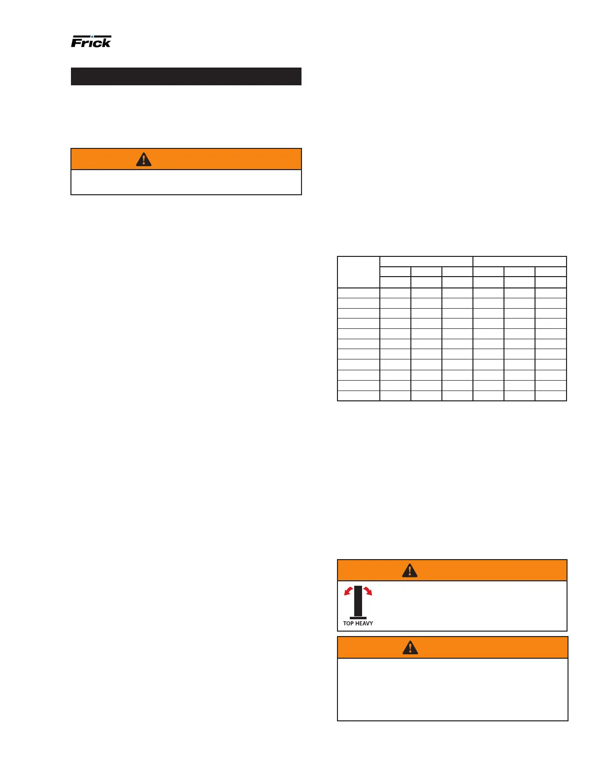
In any screw compressor installation, suction and dis-
charge lines should be supported in pipe hangers (prefer-
ably within two feet of vertical pipe run) so that the lines
won’t move if disconnected from the compressor. See
Table 2.
Table 2: Allowable ange loads
Nozzle Moments (ft-lbf) Load (lbf)
size Axial Vert. Lat. Axial Vert. Lat.
NPS MR MC ML P VC VL
1 25 25 25 50 50 50
1.25 25 25 25 50 50 50
1.5 50 40 40 100 75 75
2 100 70 70 150 125 125
3 250 175 175 225 250 250
4 400 200 200 300 400 400
5 425 400 400 400 450 450
6 1,000 750 750 650 650 650
8 1,500 1,000 1,000 1,500 900 900
10 1,500 1,200 1,200 1,500 1,200 1,200
14 2,000 1,800 1,800 1,700 2,000 2,000
Consult a licensed architect to determine the proper foun-
dation requirements for any large engine or turbine drive.
When applying screw compressors at high pressures, the
customer must be prepared for package vibration and
noise higher than the values predicted for normal refrig-
eration duty. Proper foundations and proper installation
methods are vital; and even then, sound attenuation or
noise curtains may be required to reduce noise to desired
levels.
For more detailed information on screw compressor foun-
dations, refer to 070.210-IB.
Rigging and handling
WARNING
This screw compressor package may be
top-heavy. Use caution in rigging and
handling. Improper handling could result in
serious injury or death.
WARNING
Package may contain oil. The center of gravity may
shift during rigging and handling. Mishandling or im-
proper installation can cause serious injury or death.
Oil is ammable. Avoid sources of ignition including
welding, sparks, stray currents, and static.
Installation
Foundation
If the RWF II Rotary Screw Compressor unit is shipped
mounted on a wood skid, it must be removed before
installing the unit.
WARNING
Allow space for servicing the unit per factory draw-
ings.
The rst requirement of the compressor foundation is that
it must be able to support the weight of the compres-
sor package including coolers, oil, and refrigerant charge.
Screw compressors are capable of converting large quan-
tities of shaft power into gas compression in a relatively
small space and a mass is required to effectively dampen
these relatively high-frequency vibrations.
Firmly anchoring the compressor package to a suitable
foundation by proper application of grout and elimina-
tion of piping stress imposed on the compressor is the
best insurance for a trouble-free installation. Use only
the certied general arrangement drawings from Frick
to determine the mounting foot locations and to allow
for recommended clearances around the unit for ease of
operation and servicing. Foundations must be in compli-
ance with local building codes and materials should be of
industrial quality.
The oor must be a minimum of 6 inches of reinforced
concrete and housekeeping pads are recommended.
Anchor bolts are required to rmly tie the unit to the
oor. After the unit is rigged into place (see Rigging and
handling), the feet must then be shimmed in order to level
the unit. The shims should be placed to position the feet
roughly one inch above the housekeeping pad to allow
room for grouting. An expansion-type epoxy grout must
be worked under all areas of the base with no voids and
be allowed to settle with a slight outward slope so oil and
water can run off of the base.
When installing on a steel base, the following guidelines
should be implemented to properly design the system
base:
1. Use I-beams in the skid where the screw compres-
sor will be attached to the system base. They should run
parallel to the package feet and support the feet for their
full length.
2. The compressor unit feet should be continuously welded
to the system base at all points of contact.
3. The compressor unit should not be mounted on vibra-
tion isolators in order to hold down package vibration
levels.
4. The customer’s foundation for the system base should
fully support the system base under all areas, but most
certainly under the I-beams that support the compressor
package.
When installing on the upper oors of buildings, extra
precautions should be taken to prevent normal package
vibration from being transferred to the building structure.
It may be necessary to use rubber or spring isolators, or

 Loading...