070.610-IOM (JUL 21)
Page 52
RWF II Rotary Screw Compressor Units
Maintenance
Shutdown due to improper oil
pressure (high stage and booster)
The compressor must not operate with incorrect oil
pressure.
1. Refer to Control setup - Oil setpoints display in pub-
lication 090.040-O.
Motor and bare compressor
replacement
Refer to publication 070.660-SM.
SAE straight thread o-ring ttings
assembly procedure
When performing maintenance or replacing the compres-
sor, the hydraulic tubing may need to be removed and
re-installed. The following procedure outlines the proper
installation of SAE straight thread ttings to SAE straight
thread ports.
The male and female ends of SAE straight thread O-ring
ports have UN/UNF straight threads. An elastomeric O-ring
is tted to the male end. On assembly, the O-ring is rmly
sandwiched between the angular sealing surface of the
female port and the shoulder of the male end. Sealing is
thus affected and maintained by the O-ring compression
which results from the clamping force generated by the
tightening action. The straight threads do not offer sealing
action; they provide the resistance (holding power) for
service pressure.
1. Inspect components to ensure that male and female
port threads and sealing surfaces are free of burrs, nicks
and scratches or any foreign material.
2. If the O-ring is not pre-installed to the tting on the
male end, install the proper size O-ring.
3. Lubricate the O-ring with a light coating of system oil
or petroleum jelly.
4. Screw the tting into the female port until the hex at
contacts the port face. Light wrenching may be necessary.
5. Tighten to the appropriate torque value shown in the following table.
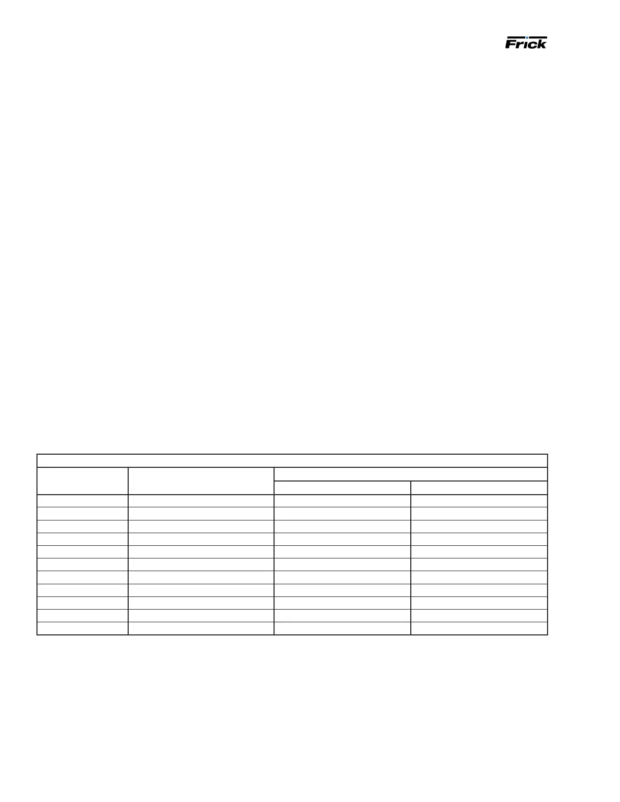
Table 18: SAE port adjustable tting or plug torque
Straight and adjustable ttings or plugs (steel)
Fitting size SAE port thread size Assembly torque
in.-lb ft-lb
2 5/16 – 24 65 ± 5 5.5 ± 0.5
3 3/8 – 24 130 ± 10 11 ± 1.0
4 7/16 – 20 170 ± 10 14 ± 1.0
5 1/2 - 20 260 ± 15 22 ± 1.0
6 9/16 – 18 320 ± 20 27 ± 2.0
8 3/4 - 16 500 ± 25 42 ± 2.0
10 7/8 – 14 720 ± 30 60 ± 2.5
12 1
1
⁄16 – 12 960 ± 50 80 ± 5.0
16 1
5
⁄16 – 12 1380 ± 75 115 ± 6.0
20 1
5
⁄8 – 12 2700± 150 225 ± 12.0
24 1
7
⁄8 - 12 3000 ± 160 250 ± 12.0

 Loading...