070.610-IOM (JUL 21)
Page 31
RWF II Rotary Screw Compressor Units
Operation
Suction check valve power assist kit
Low temperature booster compressor applications require
hot gas to assist the suction check valve closure for RWF II
models 496, 676, 856, and 1080. This is accomplished by
using the high pressure discharge gas from the high pres-
sure side of the system (power assist kit).
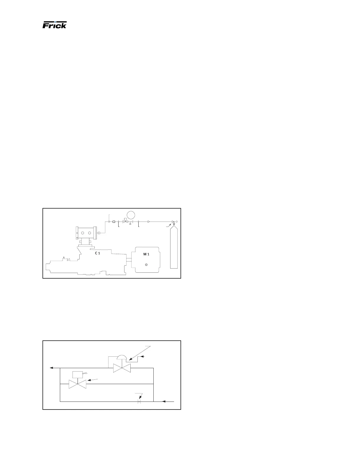
The power assist kit (see Figure 37) is factory installed
with the discharge gas pressure being supplied from the
high stage discharge gas. Running piping, rather than tub-
ing, to supply high pressure gas to the unit is recommend-
ed. The piping should be at least 3/4 in. in diameter, and
should be insulated and heat traced to prevent internal
condensation.
The power assist kit consists of a strainer, mounted and
wired solenoid valve, timer, and metering valve. The timer
limits the high pressure gas feed to the suction check
valve to thirty seconds via the solenoid valve. This is suf-
cient time to warm the suction check valve piston and
provide proper operation. The metering valve is provided
for use as a service valve and to allow discharge gas ow
regulation to prevent excessive force and resulting closure
"hammering". The valve should be adjusted accordingly to
prevent such an occurrence.
Figure 37: Power assist kit
POWER ASSIST TO BE CONNECTED TO
CONN IN CENTER OF MV END PLATE
HIGH PRESSURE GAS FROM HIG
H
E
3/8 OD
1/21/2
3/8
STR-4
S
YY
7
Balance piston pressure regulator
A Balance Piston Pressure Regulator may be required on
Models 496 to 1080 to reduce the extended overbalance
from the thrust balance piston at part load.
Figure 38 shows the three additions described below ar-
ranged in parallel.
Figure 38: High-stage SB-2 oil supply line diagram
534B0325H01 1/8" RESTRICTION ORIFICE
951A0007H01 (OR H03)
SOLENOID VALV E
TO SB-2
COMPRESSOR
PORT
954A0014H01 PRESSURE-REGULAT INGVALVE (A4ALE)
FROM
COMPRESSOR
DISCHARGE OR
OIL MANIFOLD
BLPSPREG
FROM OIL
MANIFOLD
Pressure-regulating valve: Discharge pressure determines
compressor thrust balance. The proper setting for the
pressure-regulating valve is 50 psi (±15) below discharge
pressure when slide valve is less than 65%.
Solenoid valve: Energizing, or opening, the solenoid valve
pressurizes the balance piston with full oil pressure from
the oil manifold, bypassing the A4ALE Pressure Regulating
Valve. De-energizing, or closing, the solenoid valve pres-
surizes the balance piston with oil pressure regulated by
the A4ALE Pressure Regulating Valve.
Signals from the control panel operate the solenoid valve
(output module 12 on micro panel). The solenoid valve
should open when the slide valve position is 70% or
greater, and close when the slide valve position is 65% or
less.
Orice: The orice ensures oil supply to the inlet end
bearings during upset conditions such as start-up.
Initial start-up
Initial start-up must be performed under the super vision of
a Johnson Controls-Frick authorized start-up representa-
tive to prevent voiding the compressor warranty. Before
the start-up, complete the prestart check. See the RWF II
Compressor prestart checklist in the Forms section.
Initial start-up procedure
Having performed the checkpoints on the prestart check
list (see Forms), the compressor unit is ready for start-up.
It is impor tant that an adequate refrigerant load be avail-
able to load test the unit at normal operating conditions.
The following points should be kept in mind during initial
start-up.
1. It is imperative that during the initial start-up of the
package that the hand expansion valve on the main oil
injection line is fully open to ensure adequate oil ow.
There is still an orice installed in the compressor to con-
trol maximum oil ow. At initial start-up of the package
the hand expansion valve must be fully open. After initial
start-up of the package the hand expansion valve should
be adjusted. There are two methods of determining the
correct adjustment of this valve.
The best method to determine target discharge tempera-
ture is to run CoolWare™ with the operating conditions
of the compressor. The program will give you a theoreti-
cal discharge temperature of the compressor. Once this
temperature is known, you may adjust the hand expansion
valve. The ideal discharge temperature is within 5°F + or –
of the theoretical discharge temperature. Adjust the valve
to achieve the theoretical discharge temperature. If you
do not have access to CoolWare™, 180°F is a good target
discharge temperature for a high stage ammonia compres-
sor. Booster applications and compressors using HFC and
HCFC refrigerants may run cooler. Compressors with high
discharge pressure may run hotter.
The rst method is used for compressors with external oil
cooling (thermosyphon, water cooled, and glycol cooled).
Before the initial startup of the compressor close the hand
expansion valve completely. Open the valve back up and
count the turns that it takes to fully open the valve. After
the initial startup close the valve to achieve approximately
180°F discharge temperature or the theoretical tempera-
ture from CoolWare. Do not fully close the valve at any
time while the compressor is running.

 Loading...