070.650-IOM (JUL 19)
Page 18
SGC/SGX ROTARY SCREW COMPRESSOR
INSTALLATION
590.6 [23.25]
91.2 [3.59]
327.2 [12.88]
SC-6
314.5 [12.38]
SL-2
SB-3
98.6 [3.88]
127 [5.00]
38.1 [1.50]
91.2 [3.59]
44.5 [1.75]
Ă444.5 [Ă17.50]
206.5 [8.13]
349.3 [13.75]
178.3 [7.02]
341.9 [13.46]
111 [4.37]
SD-1
97.3 [3.83]
203.2 [8.00]
804.6 [31.68]
SC-5
SC-14
197.1 [7.76]
104.6 [4.12]
365.3 [14.38]
198.6 [7.82]
139.7 [5.50]
SE-1
104.6 [4.12]
381 [15.00]
183.1 [7.21]
762 [30.00]
381 [15.00]
762 [30.00]
DISTANCE REQUIRED
FOR STRAINER REMOVAL
187.7 [7.39]
P
T
P
SB-2
30Ā
12.7 [.50]
12.7 [.50]
SB-2
819.1 [32.25]
INLET END
SCALE 1:2
SECTION A-A
A
A
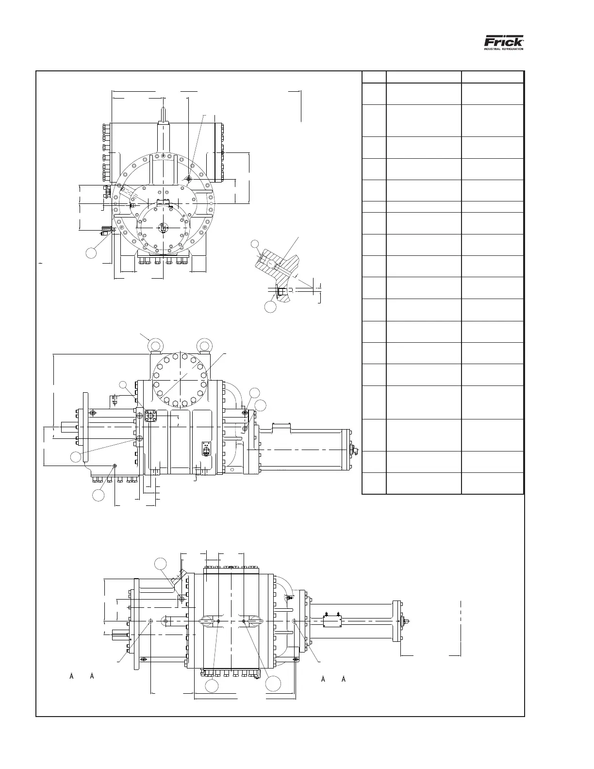
Figure 7: Port locations, SGC 2821
Port Thread size (in.) Description
P
1 1/16-12 UN-2B
straight THD O-ring
Manifold block
pressure
SB-2
1 1/16-12 UN-2B
straight THD O-ring
Balance piston
and inlet bear-
ings
SB-3 1 1/14 square flange
Compressor oil
supply
SC-5
9/16-18 UNF-2B
straight THD O-ring
Inlet pressure
SC-6
9/16-18 UNF-2B
straight THD O-ring
Discharge pres-
sure
SC-7 1/8-27 NPTF Seal weepage
SC-8
1 5/16-12 UN-2B
straight THD O-ring
Closed thread
drain
SC-9
9/16-18 UNF-2B
straight THD O-ring
Inlet housing oil
drain
SC-13
9/16-18 UNF-2B
straight THD O-ring
Oil drain cylinder
SC-14
9/16-18 UNF-2B
straight THD O-ring
Liquid injection
bleed
SD-1
1 1/16-12 UN-2B
straight THD O-ring
Coalescer bleed
SE-1 1/2-14 NPTF
Electrical con-
nector
SL-1
1 5/16-12 UN-2B
straight THD O-ring
Low Vi liquid
injection
SL-2
1 5/16-12 UN-2B
straight THD O-ring
Hi Vi liquid injec-
tion
SM-1
1 5/8-12 UN-2B
straight THD O-ring
Main oil injection
SV-1 2 1/2 square ange
Vapor injection-
tongue and
groove
TE-1 3/4-14 NPTF
Suction gas tem-
perature element
T
3/4-16 UNF-2B
straight THD O-ring
Manifold block
tank
762 [30.00]
DISTANCE REQUIRED FOR
STRAINER REMOVAL
355.6 [14.00]
DISTANCE REQUIRED FOR
TRANSMITTER REMOVAL
INSTALL A SOLID 1/2-14 NPTF
PIPE PLUG IN THIS LOCATION
WHEN USING PORT SB-2 FOR
BALANCE PISTON AND INLET
BEARING SUPPLY.
DO NOT PLUG THIS PASSAGE IF
PORT SB-2 IS NOT PIPED. BLOCK-
ING THIS PASSAGE WHEN PORT
SB-2 IS NOT PIPED CAN RESULT
IN A CATASTROPHIC FAILURE DUE
TO LACK OF OIL SUPPLIED TO
THE BALANCE PISTON AND INLET
BEARINGS.
SUCTION FLANGE
"10" CLASS 300 ANSI FLANGE
M24 X 3.0-6H
44.5 [1.75] DP 16 PL
EQUALLY SPACED ON A 387.4 [15.25] B.C.
M36 EYEBOLT FOR LIFTING (USE 2 SHOWN
WHEN MOUNTING COMPRESSOR
INLET END
TRANSDUCER
MOUNTING
SPOTFACE
31.8 [ 1.25]
1.5 [.06] DP
1/4-28 UN-2B
12.7 [.50] DP
TRANSDUCER
MOUNTING
SPOTFACE
31.8 [ 1.25]
1.5 [.06] DP
1/4-28 UN-2B
12.7 [.50] DP
965.2 [38.00]
DISTANCE REQUIRED FOR
CYLINDER REMOVAL
MOUNTING FOOTC
L
SECTION A-A
SCALE 1:2