070.650-IOM (JUL 19)
Page 40
SGC/SGX ROTARY SCREW COMPRESSOR
MAINTENANCE
TROUBLESHOOTING GUIDE (CONTINUED)
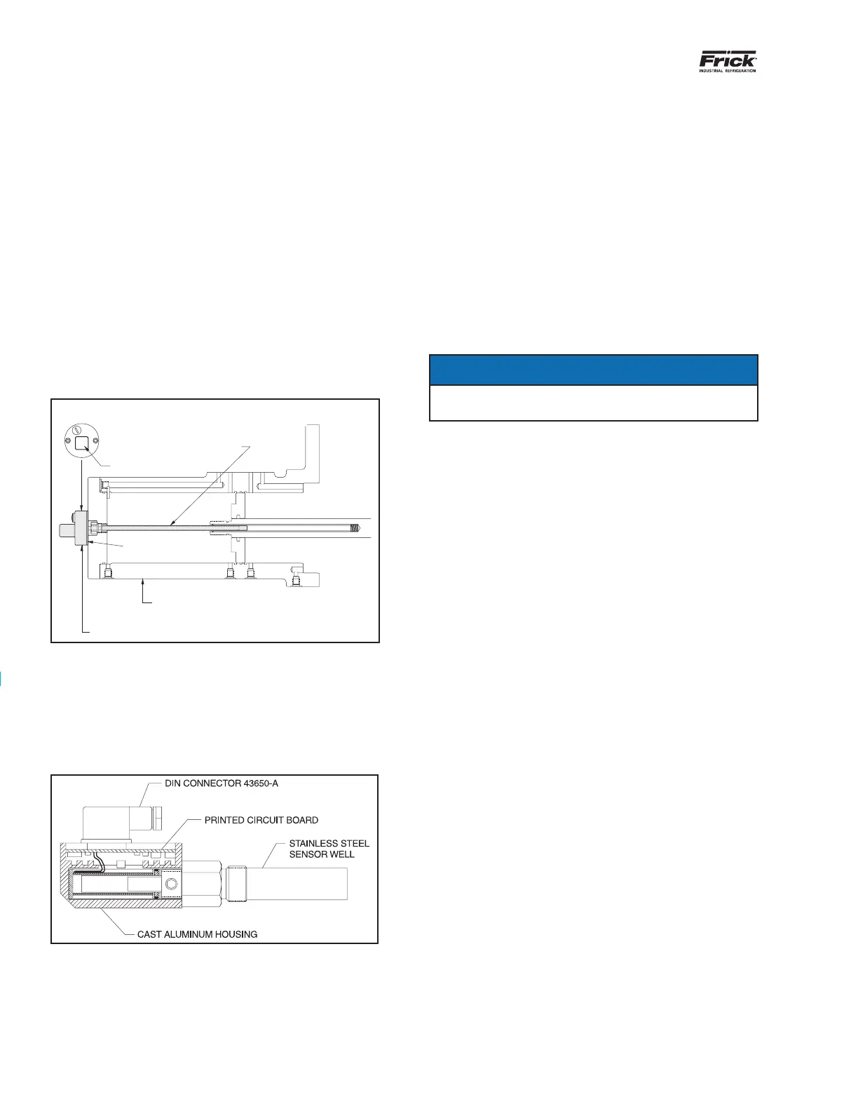
CAPACITY LINEAR TRANSMITTER REPLACEMENT -
SLIDE VALVE
The Capacity Linear Transmitter is located on the end of the
compressor cylinder (see Figure 29). The linear transmitter
with hermetic enclosure is based on the inductive measuring
principle. It features removable electronics (from the sensor
well) eliminating the need to evacuate the compressor for
replacement. This type of transmitter is dedicated to capacity
control and is not adjustable.
1. Shut off control power.
2. Remove DIN connector plug from transmitter.
3. Loosen cap screws.
4. Remove transmitter unit.
5. Install new transmitter unit.
6. Tighten cap screws.
7. Apply DIN connector plug to transmitter.
8. Turn on control power.
ENDVIEW
DIN CONNECTOR
STAINLESS STEEL WELL
HEAT ISOLATOR
CAST ALUMINUM HOUSING
COMPRESSOR UNLOAD CYLINDER
SHADED AREA SHOWS
CAPACITY LINEAR TRANSMITTER
Figure 29: Capacity linear transmitter
VOLUMIZER
®
TRANSMITTER REPLACEMENT - SLIDE
STOP
The VOLUMIZER
®
Transmitter is located on the right side
of the compressor (facing shaft) at the inlet end (see
Figure 30).
Figure 30: Volumizer
®
transmitter
The linear transmitter, with hermetic enclosure is based
on the inductive measuring principle. It features removable
electronics (from the sensor well) eliminating the need to
evacuate the compressor for replacement. This type of
transmitter is dedicated to volume ratio control and has no
user adjustments.
1. Shut off control power.
2. Remove DIN connector plug from transmitter.
3. Loosen setscrews.
4. Remove transmitter unit.
5. Install new transmitter unit.
6. Tighten setscrews.
7. Apply DIN connector plug to transmitter.
8. Turn on control power.
Notice
For calibration of the Volumizer
®
unit, refer to the Analog
Calibration instructions in publication 090.040-O.
BARE COMPRESSOR REPLACEMENT
The following procedure is required only when replacing a
barecompressorintheeldthathasnomotortunnel:
1. Verify that the starter is locked out.
2. Remove all tubing, piping, and wiring that is connected
to the compressor.
3. Disconnect the coupling from the motor shaft.
4. While supporting the motor and compressor assembly
with a crane, remove the bolts at the compressor feet.
5. Thoroughly clean the compressor feet and mounting
padsofburrsandotherforeignmattertoensurerm
seating of the compressor.
6. Thoroughly clean the new compressor and remove all
cover plates and protection.
7. Install new gaskets and sealing in all connections.
8. Set the new compressor in place and shim feet where
required.
9. Reattach the drive coupling.
10. Check the shaft alignment.
11. Complete tubing, piping, and wiring.
Note: Refer to 070.660-SM - Bare Rotary Screw Compres-
sor Replacement when a motor tunnel is installed.
SHUTDOWN DUE TO IMPROPER OIL PRESSURE
(HIGH STAGE AND BOOSTER)
The compressor must not operate with incorrect oil pressure.
1. Refer to CONTROL SETUP