070.650-IOM (JUL 19)
Page 3
SGC/SGX ROTARY SCREW COMPRESSOR
INSTALLATION - OPERATION - MAINTENANCE
Notice
The information contained in this document is sub-
ject to change without notice.
General information
PREFACE
This manual describes the installation, operation, and
maintenance procedures of SGC, SGCB/H, and SGXB/H
Rotary Screw Compressors (referred to in this document
as SGC or SGX). The term SGC refers to the 1913, 1918,
2313, 2317, 2321, 2813, 2817, 2821, and 2824 SGC units, as
well as the 3511, 3515, and 3519 SGCB and SGCH units. The
term SGX refers to the 3519, 4013, 4018, and 4021 SGXB
and SGXH units, as well as the 3524 SGXB unit.
It is important that these compressors are properly applied
to an adequately controlled refrigerant or gas system.
Consult your authorized Johnson Controls-FRICK represen-
tative for expert guidance in this determination.
Proper performance and continued satisfaction with these
units is dependent upon:
• Correct installation
• Proper operation
• Regular and systematic maintenance
To ensure correct installation and application, select the
appriopriate equipment and connect to a properly de-
signed and installed system. The engineering plans, piping
layouts, and other system design materials, must be
detailed in accordance with the best practices and local
codes, such as those outlined in ASHRAE literature.
A screw compressor is a vapor pump. To ensure that
workinguidintheliquidstateisnotbeingingested,
peform the following steps:
• Select controls carefully. Ensure they are in good oper-
ating condition.
• Properly size piping and correctly arrange traps, if they
are necessary.
• Check that the suction line has an accumulator or slug-
ging protection.
• Know the load surges and make provisions for control.
• Check that operating cycles and stand still periods are
reasonable.
• Size high side components within the system and com-
pressor design limits.
It is necessary to keep the discharge temperature high
enough to prevent condensation of any moisture in the
compressor and oil separator.
DESIGN LIMITATIONS
SGC/SGX compressors are designed for operation within
thepressureandtemperaturelimitsspeciedbyJohnson
Controls-FRICK and the Johnson Controls-FRICK selection
software CoolWare
™
. They are primarily used for com-
pressing refrigerant gas and most hydrocarbon gasses.
If your application is for sour gas, there are special re-
quirements to protect the compressor. Contact Johnson
Controls-FRICK Compressor Engineering for application
details.
JOB INSPECTION
Immediately upon delivery examine all crates, boxes, and
exposed compressor and component surfaces for damage.
Unpack all items and check against shipping lists for any
discrepancy. Examine all items for damage in transit.
STANDARD BARE COMPRESSOR
Items not included with bare compressor that are available
as sales order options:
• Motor mount
• Solenoid valve block
• Solenoid valves
• Tank drain tubing (T connection)
• Oil feed line (P connection)
• Connectionttings
• Coupling
TRANSIT DAMAGE CLAIMS
All claims must be made by consignee. This is an ICC
requirement. Request immediate inspection by the agent
of the carrier and be sure the proper claim forms are ex-
ecuted. Report damage or shortage claims immediately to
Johnson Controls-FRICK Sales Administration Department,
in Waynesboro, PA.
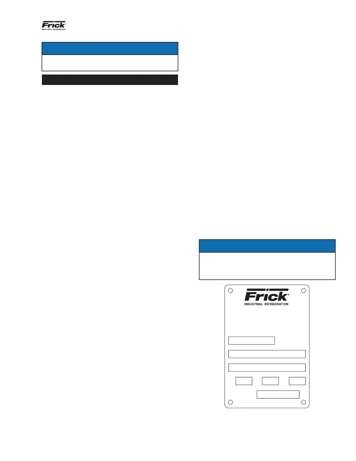
COMPRESSOR IDENTIFICATION
Each compressor has an identicationdataplate,contain-
ing compressor model and serial number, mounted on the
compressor body.
Notice
When inquiring about the compressor or unit, or
ordering repair parts, provide the model and serial
numbers from the data plate (see Figure 1) as well as
the Johnson Controls-FRICK sales order numbers.
Figure 1: Identication data plate
100 CUMBERLAND VALLEY AVENUE
WAYNESBORO, PA 17268
ROTARY SCREW COMPRESSOR
MODEL NO.
MAX DRIVER SPEED MAX ALLOWABLE PRESSURE
PART NO.
RPM
PSIG
BARG
ASSEMBLED IN
FROM FOREIGN AND DOMESTIC MATERIALS
SERIAL NO.