5
Parameters in the Setup Menu for Field Adjus-
table Trip Points
Voltage Limit
Values
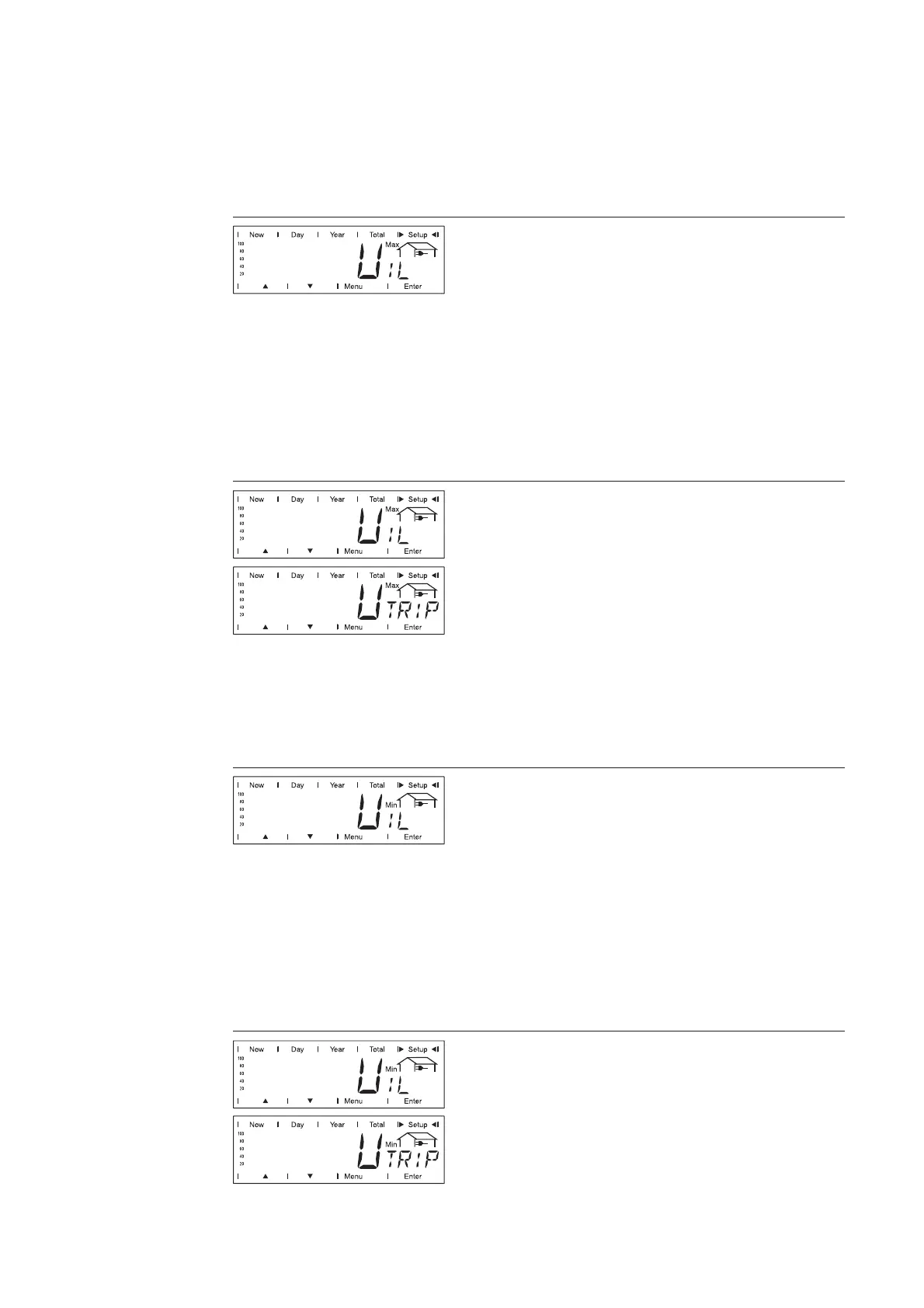
Maximum inner limit voltage
Upper limit voltage between the AC terminals
of the inverter
Unit V
Setting range 106 - 248 at 208 V grid voltage
122 - 287 at 240 V grid voltage
141 - 324 at 277 V grid voltage
Factory setting 229 at 208 V grid voltage
264 at 240 V grid voltage
305 at 277 V grid voltage
Maximum inner limit voltage trip time
Time duration in which exceeding the upper
limit voltage is allowed. When the upper limit
voltage is exceeded longer than the set time,
the inverter stops supplying energy to the
grid.
The display switches between ‘UIL
Max
’ and
‘UTRIP
Max
’.
Unit P (grid cycles)
Setting range 1 - 255 at 208 V / 240 V / 277 V grid voltage
Factory setting 58 at 208 V / 240 V / 277 V grid voltage
Minimum inner limit voltage
Lower limit voltage between the AC terminals
of the inverter
Unit V
Setting range 105 - 247 at 208 V grid voltage
121 - 286 at 240 V grid voltage
140 - 323 at 277 V grid voltage
Factory setting 183 at 208 V grid voltage
211 at 240 V grid voltage
244 at 277 V grid voltage
Minimum inner limit voltage trip time
Time duration in which going below the lower
limit voltage is allowed. When the system
goes below the lower limit voltage longer than
the set time, the inverter stops supplying
energy to the grid.
The display switches between ‘UIL
Min
’ and
‘UTRIP
Min
’.